 Development Environment Introduction:Main Control: ESP32S3N16R8 ModuleEnvironment: Developed under ESP-IDF V5.3 FrameworkRF Module: 2.4G RF Module, Model E01C-ML01DP5Communication Interface: SPI
 RF Module Introduction:This time, we are using the 2.4G RF module based on Si24R1 from the brand Yibait.Si24R1 is pin-compatible with nRF24L01 and is a commonly used domestic alternative to nRF24L01. The driving method is also basically the same as that of nRF24L01. Due to its higher cost-performance ratio, modules based on this chip are still quite common in the market.This article will only discuss the core points of driving Si24R1 in the ESP-IDF environment. As for the details of using the Si24R1 chip in various aspects, the author will provide a separate article to explain.
 SPI Driver Writing:
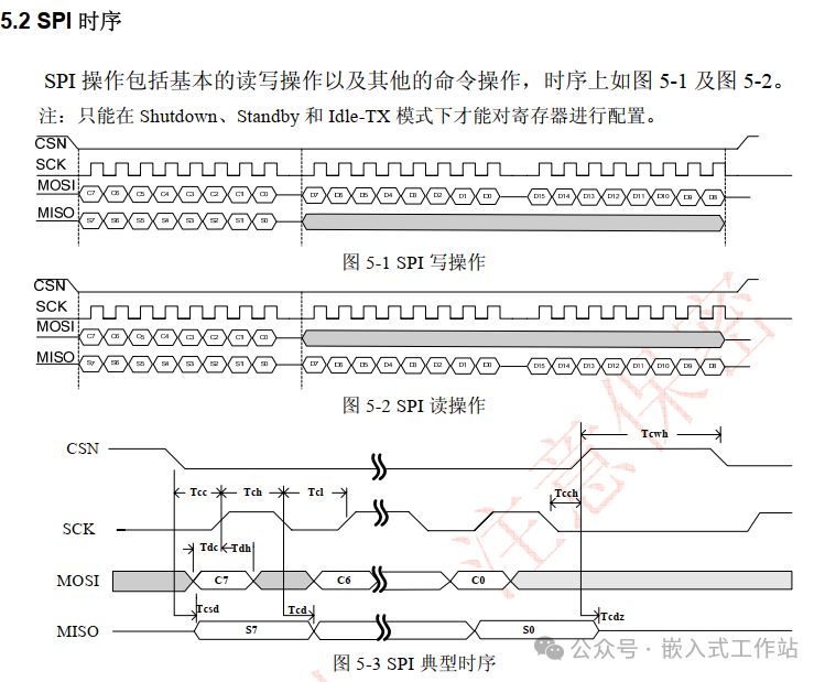 Above is the SPI timing diagram of Si24R1.
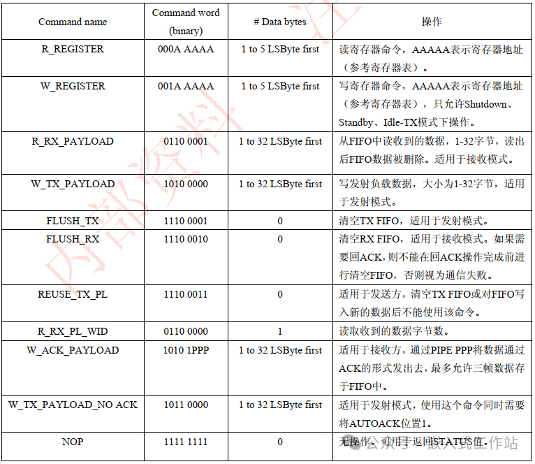 Above is the operational commands supported by Si24R1.It can be seen that all operations first send the command byte, followed by the data byte. If there are no data bytes, only the command byte needs to be sent. Moreover, during a single operation, CSN must remain low.If we use hardware chip selection, then a separate data buffer generally needs to be established in the interface packaging to concatenate the command and data, and send them together. The author finds this cumbersome, memory-wasting, and lacking compatibility, so I choosesoftware chip selection.For SPI bus driver reference:
/* Pin Definitions */#define SPI3_CLK_GPIO_PIN    GPIO_NUM_41  /* SPI1_CLK */#define SPI3_MOSI_GPIO_PIN   GPIO_NUM_42  /* SPI1_MOSI */#define SPI3_MISO_GPIO_PIN   GPIO_NUM_2   /* SPI1_MISO */
// Initialize SPI Bus
void spi_bus_init(spi_host_device_t host_id){  spi_bus_config_t spi_bus_conf = {0};  spi_bus_conf.miso_io_num = SPI3_MISO_GPIO_PIN;  spi_bus_conf.mosi_io_num = SPI3_MOSI_GPIO_PIN;  spi_bus_conf.sclk_io_num = SPI3_CLK_GPIO_PIN;  /* SPI write protection signal pin, this pin is not enabled */  spi_bus_conf.quadwp_io_num = -1;  /* SPI hold signal pin, this pin is not enabled */  spi_bus_conf.quadhd_io_num = -1;  /* Configure maximum transfer size, in bytes */  spi_bus_conf.max_transfer_sz = 128;      ESP_ERROR_CHECK(spi_bus_initialize(SPI3_HOST, &spi_bus_conf, SPI_DMA_CH_AUTO));}
In the ESP-IDF framework, the new versions of SPI, IIC, and other drivers adopt a bus-device model similar to Linux. We first need to initialize the SPI bus; here I am using SPI3, and everyone can modify it according to their situation.Si24R1 has a maximum single-frame data size of 32 bytes, so I setmax_transfer_sz slightly larger.For SPI low-level read/write interface reference:
// SPI Send Command
// handle : SPI device handle
// cmd    : command to be sent
void spi_write_cmd(spi_device_handle_t handle, uint8_t cmd){    spi_transaction_t t = {0};    /* Number of bits to be transmitted, one byte 8 bits */    t.length = 8;       /* Fill in the command */                                        t.tx_buffer = &cmd;                                     /* Start transmission */    ESP_ERROR_CHECK(spi_device_polling_transmit(handle, &t));}
// SPI Send Data
// handle : SPI device handle
// data   : data to be sent
// len    : length of data to be sent
void spi_write_data(spi_device_handle_t handle, const uint8_t *data, int len){    spi_transaction_t t = {0};    if(data==NULL || len == 0){ return; }    /* Number of bits to be transmitted, one byte 8 bits */    t.length = len * 8;                                 /* Fill in the command */    t.tx_buffer = data;                                 /* Start transmission */    ESP_ERROR_CHECK(spi_device_polling_transmit(handle, &t));}
// SPI Transfer Data
// handle : SPI device handle
// data   : data to be sent
// retval : received data
uint8_t spi_transfer_byte(spi_device_handle_t handle, uint8_t data){    spi_transaction_t t;    memset(&t, 0, sizeof(t));    t.flags = SPI_TRANS_USE_TXDATA | SPI_TRANS_USE_RXDATA;    t.length = 8;    t.tx_data[0] = data;    spi_device_transmit(handle, &t);    return t.rx_data[0];}
For SPI device driver reference:
spi_device_handle_t My_Radio_Handle;
#define RADIO_IO_CS GPIO_NUM_40
#define RADIO_IO_CE GPIO_NUM_39
#define RADIO_IO_IRQ GPIO_NUM_1
#define RADIO_CE(x) do{ x ? \
(gpio_set_level(RADIO_IO_CE, 1)): \
(gpio_set_level(RADIO_IO_CE, 0)); \
}while(0)
#define RADIO_CS(x) do{ x ? \
(gpio_set_level(RADIO_IO_CS, 1)): \
(gpio_set_level(RADIO_IO_CS, 0)); \
}while(0)
// Send completion flag, set in the send interrupt
static uint8_t L01_TxDone = 0;
// Interrupt callback
static void IRAM_ATTR exit_gpio_isr_handler(void *arg){ uint32_t gpio_num = (uint32_t) arg; if(gpio_num == RADIO_IO_IRQ){ L01_TxDone = 1; }}
// IO Pin Initialization
void Radio_IO_Init(void){ gpio_config_t gpio_init_struct; /* SPI device interface configuration */ spi_device_interface_config_t devcfg = { /* SPI communication frequency, maximum support 10Mz */ .clock_speed_hz = 8 * 1000 * 1000, /* SPI clock */ /* Choose mode 0 according to the above timing diagram */ .mode = 0, /* SPI Mode 0 */ /* Use software chip select */ .spics_io_num = -1, //RADIO_IO_CS, /* SPI device pin */ .queue_size = 3, /* Transaction queue size 3 */ }; /* Add SPI bus device */ ESP_ERROR_CHECK(spi_bus_add_device(SPI3_HOST, &devcfg, &My_Radio_Handle)); /* CS Pin */ gpio_init_struct.mode = GPIO_MODE_OUTPUT; /* Configure output mode */ gpio_init_struct.intr_type = GPIO_INTR_DISABLE; /* Disable pin interrupt */ gpio_init_struct.pin_bit_mask = 1ull << RADIO_IO_CS; /* Configure pin bit mask */ gpio_init_struct.pull_down_en = GPIO_PULLDOWN_DISABLE; /* Disable pull-down */ gpio_init_struct.pull_up_en = GPIO_PULLUP_DISABLE; /* Enable pull-up */ gpio_config(&gpio_init_struct); /* Pin configuration */ RADIO_CS(1); /* CE Pin */ gpio_init_struct.mode = GPIO_MODE_OUTPUT; /* Configure output mode */ gpio_init_struct.intr_type = GPIO_INTR_DISABLE; /* Disable pin interrupt */ gpio_init_struct.pin_bit_mask = 1ull << RADIO_IO_CE; /* Configure pin bit mask */ gpio_init_struct.pull_down_en = GPIO_PULLDOWN_DISABLE; /* Disable pull-down */ gpio_init_struct.pull_up_en = GPIO_PULLUP_DISABLE; /* Enable pull-up */ gpio_config(&gpio_init_struct); /* Pin configuration */ RADIO_CE(CE_LOW); /* IRQ Pin */ gpio_init_struct.mode = GPIO_MODE_INPUT; gpio_init_struct.intr_type = GPIO_INTR_NEGEDGE; /* Falling edge interrupt */ gpio_init_struct.pull_down_en = GPIO_PULLDOWN_DISABLE; /* Disable pull-down */ gpio_init_struct.pull_up_en = GPIO_PULLUP_ENABLE; /* Enable pull-up */ gpio_init_struct.pin_bit_mask = 1ull << RADIO_IO_IRQ; gpio_config(&gpio_init_struct); /* Register interrupt service */ gpio_install_isr_service(ESP_INTR_FLAG_EDGE); /* Set GPIO interrupt callback function */ gpio_isr_handler_add(RADIO_IO_IRQ, exit_gpio_isr_handler, (void*)RADIO_IO_IRQ); /* Enable GPIO module interrupt signal */ gpio_intr_enable(RADIO_IO_IRQ);} SPI Command Interface Implementation:We need to implement the command interface for Si24R1, and can implement only part of it as needed, as follows:
// SPI Write Command
static void L01_WriteCmd(uint8_t cmd, uint8_t *data, uint8_t size){ RADIO_CS(0); spi_write_cmd(My_Radio_Handle, cmd); if(data != NULL && size > 0){ spi_write_data(My_Radio_Handle, data, size); } RADIO_CS(1);}
// SPI Read Command
static void L01_ReadCmd(uint8_t cmd, uint8_t *data, uint8_t size){ RADIO_CS(0); spi_write_cmd(My_Radio_Handle, cmd); for(uint8_t i = 0; i < size; i++){ *(data + i) = spi_transfer_byte(My_Radio_Handle, NOP); } RADIO_CS(1);}
/*********************************************************/
// Read Multiple Registers
static void L01_ReadMultiReg(uint8_t reg, uint8_t *data, uint8_t size){ L01_ReadCmd(R_REGISTER | reg, data, size);}
// Write Multiple Registers
static void L01_WriteMultiReg(uint8_t reg, uint8_t *data, uint8_t size){ L01_WriteCmd(W_REGISTER | reg, data, size);}
// Read Single Register
static uint8_t L01_ReadSingleReg(uint8_t reg){ uint8_t data; L01_ReadMultiReg(reg, &data, 1); return data;}
// Write Single Register
static void L01_WriteSingleReg(uint8_t reg, uint8_t data){ L01_WriteMultiReg(reg, &data, 1);}
// Clear TX FIFO
static void L01_FlushTX(void){ L01_WriteCmd(FLUSH_TX, NULL, 0);}
// Clear RX FIFO
static void L01_FlushRX(void){ L01_WriteCmd(FLUSH_RX, NULL, 0);}
// Read the number of received data bytes
static uint8_t L01_ReadRXPayloadSize(void){ uint8_t datalen=0; L01_ReadCmd(R_RX_PL_WID, &datalen, 1); return datalen;}
// Read the valid data received and return the data length
static uint8_t L01_ReadRXPayload(uint8_t *data){ uint8_t datalen; // Read data length, exceeding is an exception
datalen = L01_ReadRXPayloadSize(); if(datalen > 32){ L01_FlushRX(); return 0; } // Read data
L01_ReadCmd(R_RX_PAYLOAD, data, datalen); // Clear rxbuf
L01_FlushRX(); return datalen;}
// Write TX Payload into data pipeline, PRX will return ACK
static void L01_WriteTXPayload_Ack(uint8_t *data, uint8_t size){ if(size > 32){ size = 32; } if(size == 0){ return; } L01_FlushTX(); L01_WriteCmd(W_TX_PAYLOAD, data, size);}
// Write TX Payload into data pipeline, PRX will not return ACK
static void L01_WriteTXPayload_NoAck(uint8_t *data, uint8_t size){ if(size > 32){ size = 32; } if(size == 0){ return; } L01_FlushTX(); L01_WriteCmd(W_TX_PAYLOAD_NOACK, data, size);}
// Suitable for the receiver, sending data through ACK via PIPE PPP, allowing up to three frames of data to be stored in FIFO
static void L01_WriteRXPayload_InAck(uint8_t *data, uint8_t size){ uint8_t i; if(size > 32){ size = 32; } if(size == 0){ return; } L01_WriteCmd(W_ACK_PAYLOAD, data, size);} Other Interface Implementations:In the completed driver, it is also necessary to set power, set channels, set CRC, and other series of interfaces. Here, the author only provides a data sending interface and the parameter setting interfaces involved, which can be used as a reference for everyone to implement according to their needs. Si24R1 is quite simple to use among RF chips; as long as you master its state transition diagram, the corresponding operation interfaces can be easily implemented.Additionally, pay attention to the delays between various state transitions, allowing a little margin in the software.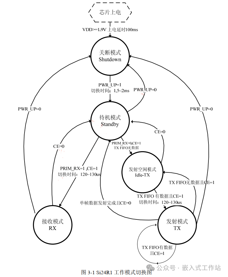
// Clear Interrupt
// bit4: MAX_RT interrupt when the maximum retransmission count is reached, write '1' to clear
// bit5: TX_DS send completion interrupt, if in ACK mode, TX_DS is set to '1' after receiving the ACK confirmation signal, write '1' to clear
// bit6: RX_DR RX FIFO has value flag, write '1' to clear
// Others: do not touch
static void L01_ClearIRQ(uint8_t irqMask){ uint8_t status = 0; irqMask &= IRQ_ALL; status = L01_ReadSingleReg(L01REG_STATUS); L01_WriteSingleReg(L01REG_STATUS, irqMask | status);}
// Set Power
static void L01_SetPower(L01_PWR power){ uint8_t mask = L01_ReadSingleReg(L01REG_RF_SETUP) & ~0x07; switch (power) { case POWER_N_18: mask |= PWR_N_18DB; break; case POWER_N_12: mask |= PWR_N_12DB; break; case POWER_N_6: mask |= PWR_N_6DB; break; case POWER_N_0: mask |= PWR_N_0DB; break; default: break; } L01_WriteSingleReg(L01REG_RF_SETUP,mask);}
// Set Frequency, range: 0-125, 2400Mhz-2525Mhz
static void L01_WriteHoppingPoint(uint8_t freq){ L01_WriteSingleReg(L01REG_RF_CH, freq <= 125 ? freq : 125);}
// Set Mode
static void L01_SetMode(L01_MODE mode){ uint8_t mask = L01_ReadSingleReg(L01REG_CONFIG); // Can only change in Shutdown and Standby
if(mode == TX_MODE) { mask &= ~(1 << PRIM_RX); } // Can only change in Shutdown and Standby
else if(mode == RX_MODE) { mask |= (1 << PRIM_RX); } // Set the PWR_UP bit value of the CONFIG register to 0, the chip immediately returns to Shutdown working mode
else if(mode == PWRDOWN_MODE) { mask &= ~(1 << PWR_UP); } // In Shutdown mode, set the PWR_UP bit value of the CONFIG register to 1, after 1.5~2ms enter Standby mode
else if(mode == PWRUP_MODE) { mask |= (1 << PWR_UP); } L01_WriteSingleReg(L01REG_CONFIG,mask);}
// Set CRC check, if enabled, it is 2-byte CRC, single byte is not considered
// If EN_AA is not all zero (enabled automatic acknowledgment for data pipelines 0-5), CRC must be enabled
static void L01_SetCrc(bool enable){ uint8_t mask = L01_ReadSingleReg(L01REG_CONFIG); if(enable == true){ mask |= (1 << EN_CRC); mask |= (1 << CRCO); }else{ mask &= ~(1 << EN_CRC); } L01_WriteSingleReg(L01REG_CONFIG, mask);}
// Radio Send
void Radio_Send(uint8_t *txaddr, uint8_t freq, L01_PWR power, L01_DRATE drate, bool crc, uint8_t *src, uint16_t ssize){ uint16_t index; // Set the sender address, default length of 5 bytes, if you need to change, you must first set the L01REG_SETUP_AW register
//L01_WriteSingleReg(L01REG_SETUP_AW, AW_4BYTES); L01_WriteMultiReg(L01REG_TX_ADDR, txaddr, 5); // Enable command W_TX_PAYLOAD_NOACK
// Default dynamic payload length is off
// Default ACK payload (ACK packet with payload data) is off
L01_WriteSingleReg(L01REG_FEATURE, 0x01<<EN_DYN_ACK); // Set channel
L01_WriteHoppingPoint(freq); // Communication rate
L01_SetDataRate(drate); // Set sending power
L01_SetPower(power); // Set CRC
L01_SetCrc(crc); // Clear all FIFO and interrupts
L01_FlushRX(); L01_FlushTX(); L01_ClearIRQ(IRQ_ALL); // Set TxMode, pull CE high, FIFO has no data, at this time will enter Idle-TX working mode
L01_SetMode(TX_MODE); RADIO_CE(CE_HIGH); // In Idle-TX mode, if TXFIFO has data and CE=1, it will automatically enter Tx mode to send data, after sending it will return to Idle-TX mode, until CE=0, it will switch to Standby mode
for(index = 0; index < ssize/32; index ++) { L01_TxDone = 0; L01_WriteTXPayload_NoAck(&src[index * 32], 32); for(uint8_t i=0; i<5; i++){ if(L01_TxDone == 1){ break; } vTaskDelay(10/portTICK_PERIOD_MS); } L01_FlushTX(); L01_ClearIRQ(IRQ_ALL); } // After data transmission, return to Standby mode
RADIO_CE(CE_LOW);}
// Radio Initialization
void NRF24L01_Init(void){ RADIO_CE(CE_LOW); L01_SetMode(PWRUP_MODE); vTaskDelay(10/portTICK_PERIOD_MS);// Enter Standby mode L01_ClearIRQ(IRQ_ALL);// Clear all interrupts } Routine Testing:Finally, write a routine as a sending test, and the receiving side uses a USB to NRF24L01 module to simply observe through a serial debugging assistant (communication parameters have been matched).
void task_radio(void *pvParameters){ uint8_t txaddr[5]={0xA5,0xA5,0xA5,0xA5,0xA5}; uint8_t txbuf[32] = {9,1,2,3,4,5,6,7,8,9}; // Power on xl9555_pin_write(RADIO_PW_IO, 0); // At least delay 100ms after the chip is powered on vTaskDelay(200/portTICK_PERIOD_MS); // Initialization NRF24L01_Init(); while(1) { printf("radio send, len:%d, data:\r\n",sizeof(txbuf)); for(uint8_t i=0; i<sizeof(txbuf); i++){ printf("%02X ", txbuf[i]); } printf("\r\n\r\n"); NRF24L01_Send(txaddr, 0, POWER_N_18, DRATE_2M, true, txbuf, sizeof(txbuf)); vTaskDelay(1000/portTICK_PERIOD_MS); } vTaskDelete(NULL);}<img src=”https://mmbiz.qpic.cn/sz_mmbiz_png/HZGaT9LlRe7Qn4QiaibtCZGG4txoCGY5LTONOffAeicWgwbgWLEKxicEFQ4BgnEZvlXdlXo5Tib7urDqqp7E6dicibAhA/640?wx_fmt=png&from=appmsg&randomid=om4n9rfp&watermark=1″