“This article focuses on the system timer (SYSTIMER) of the ESP32-S3, introducing its 52-bit counting unit, three comparison channels, and clock source characteristics. It explains the working principle based on clock division and counting comparison, and demonstrates its application in precise timing and interrupt triggering through an LED blinking example.”

01
—
Introduction to SYSTIMER
The system timer (SYSTIMER) is a multifunctional 52-bit timer unit integrated within the ESP32-S3, providing high-resolution, low-jitter timing and alarm mechanisms for real-time operating systems, applications, and low-power management.
1. Quantity and Composition:
-
It includes a set of SYSTIMER peripherals.
-
Two 52-bit incrementing counters: UNIT0, UNIT1;
Three 52-bit comparators: TARGET0, TARGET1, TARGET2 (hereinafter referred to as COMP0, COMP1, COMP2).
From an application perspective, there are three independent comparison channels that can generate interrupts, all sourced from the same counting clock.
2. Application Scenarios
-
Real-time operating system ticks (FreeRTOS defaults to using COMP0);
-
Single precise timing (timeout detection, one-time task scheduling);
-
Periodic tasks (LED blinking, sampling triggers, software PWM);
-
Time compensation after deep-sleep wake-up;
-
High-resolution performance counting (microsecond-level timing measurement).
3. Clock Source
-
Main clock: XTAL_CLK (40 MHz crystal oscillator);
-
Internal fixed divider: DIV = 2.5, generating a 16 MHz counting clock CNT_CLK;
-
Resolution: 1 / 16 MHz ≈ 62.5 ns;
-
Counter bit width: 52 bits, maximum count value 2^52-1, corresponding to approximately 2.27 years.
4. Hardware Resources
SYSTIMER is entirely located within the chip and does not occupy any GPIO. If timing events need to be output to pins, a regular GPIO can be toggled in the interrupt service routine.
5. Functional Features
-
52-bit counter, supports reading low 32 bits and high 20 bits;
-
Each comparator can be individually enabled/disabled;
-
Supports both one-time and periodic alarm modes;
-
In periodic mode, the period register is 26 bits, with a maximum period of approximately 1.07 seconds;
-
Three independent interrupt sources routed to the CPU via the interrupt matrix;
-
Supports retaining count values during deep-sleep for time compensation after wake-up.
02
—
SYSTIMER Principles
1. Functional Block Diagram
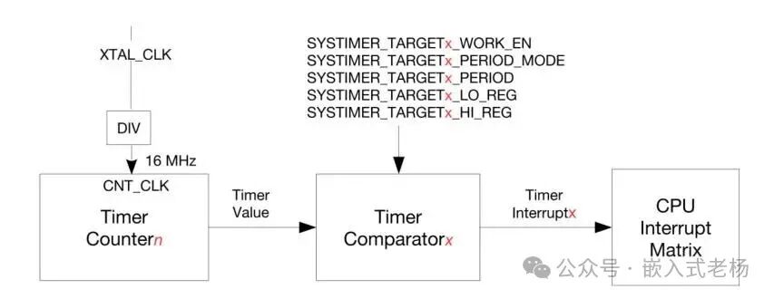
-
XTAL_CLK (Crystal Clock): The fundamental clock source for the system timer, typically provided by an external crystal oscillator, offering a stable clock signal that serves as the reference timing for the entire system timer operation.
-
DIV (Divider): Performs division on XTAL_CLK to obtain a 16MHz CNT_CLK clock signal, used to drive the timer counter operation. The clock frequency can be adjusted as needed to accommodate different timing precision and range requirements.
-
Timer Counter: Driven by the CNT_CLK clock, it continuously accumulates count values, generating a continuously changing Timer Value, which is the core counting component for the system timer’s timing functionality.
-
Timer Comparator: Receives the Timer Value from the Timer Counter and, based on a series of configured register parameters (SYSTIMER_TARGETx_WORK_EN, SYSTIMER_TARGETx_PERIOD_MODE, SYSTIMER_TARGETx_PERIOD, SYSTIMER_TARGETx_LO_REG, SYSTIMER_TARGETx_HL_REG, etc.), determines whether the Timer Value meets the set comparison conditions (such as matching the target count value). When conditions are met, it generates a Timer Interruptx (timer interrupt signal).
-
CPU Interrupt Matrix: Receives the Timer Interruptx signal from the Timer Comparator, manages and distributes the interrupt, routing the interrupt signal to the appropriate interrupt handling module in the CPU, allowing the CPU to respond to and process the interrupt events generated by the system timer.
2. Working Principle
XTAL_CLK serves as the fundamental clock source, divided by DIV to 16MHz CNT_CLK, which drives the Timer Counter to continuously count and generate Timer Value; the Timer Comparator compares the Timer Value with the set target values based on the configured register parameters. When conditions are met, it triggers the Timer Interruptx signal; this interrupt signal is sent to the CPU Interrupt Matrix, which manages and distributes the interrupt, ultimately allowing the CPU to respond to the interrupt, thus achieving the timing alarm and interrupt triggering functionality of the system timer based on clock counting and comparison mechanisms, providing precise timing and event triggering capabilities for the system.
03
—
Programming Example
Program Function:
The LED connected to GPIO1 will blink continuously with a period of one second, and the serial monitor will output log information once per second.
Implementation Process:
-
Hardware initialization;
-
System timer object creation;
-
Start periodic timer;
-
Interrupt triggering and callback execution;
-
Level toggling to achieve blinking.
#include <stdio.h>
#include "freertos/FreeRTOS.h"
#include "freertos/task.h"
#include "driver/gpio.h"
#include "esp_log.h"
#include "esp_timer.h"
#define LED_GPIO_NUM 1                       /* LED connected to GPIO1 */
#define BLINK_PERIOD_US 500000               /* Period 0.5 seconds, corresponding to once per second toggle */
static const char TAG[] = "SYSTIMER_LED";
/* Timer callback function: toggle LED level */
static void led_toggle_callback(void *arg){
    gpio_set_level(LED_GPIO_NUM, !gpio_get_level(LED_GPIO_NUM));
}
/* Configure GPIO1 as push-pull output and initialize to high level */
static void led_gpio_initialize(void){
    gpio_config_t io_conf = {
        .pin_bit_mask = (1ULL << LED_GPIO_NUM),
        .mode         = GPIO_MODE_OUTPUT,
        .pull_up_en   = GPIO_PULLUP_DISABLE,
        .pull_down_en = GPIO_PULLDOWN_DISABLE,
        .intr_type    = GPIO_INTR_DISABLE
    };
    gpio_config(&io_conf);
    gpio_set_level(LED_GPIO_NUM, 1);   /* High level turns off */
}
/* Main function entry */
void app_main(void){
    led_gpio_initialize();
    /* Create system timer handle */
    esp_timer_handle_t periodic_timer;
    esp_timer_create_args_t timer_args = {
        .callback = led_toggle_callback,
        .arg      = NULL,
        .name     = "led_blink"
    };
    ESP_ERROR_CHECK(esp_timer_create(&timer_args, &periodic_timer));
    /* Start periodic mode, period is BLINK_PERIOD_US microseconds */
    ESP_ERROR_CHECK(esp_timer_start_periodic(periodic_timer, BLINK_PERIOD_US));
    /* Main loop remains idle, LED toggling is completed by system timer interrupt callback */
    while (true) {
        vTaskDelay(pdMS_TO_TICKS(1000));
    }
}
Software and Hardware Description Used in This Example:
1. SOC Model: ESP32-S3-N16R8;
2. Software Development Environment: ESP-IDF 5.3.1, VSCode IDE (VSCodeUserSetup-x64-1.102.1 version);
3. ESP32 Project Version: IDF version (FreeRTOS);
4. Program Download: Type C USB (USB to serial) interface;
5. This software and hardware example is for personal learning only and may not be used for commercial purposes.
References:
“ESP32-S3 Technical Reference Manual Version 1.7”;
“ESP32-S3 Series Chip Technical Specification Version 2.0”.