Reading Notes: The Definitive Guide to Cortex-M3
Note: The content of this article is excerpted from the “Cortex-M3” definitive guide. The Cortex-M series is essential in embedded development, and this series will record the key points of knowledge focused on during reading, recommending the original book.
The Cortex-M3 is a 32-bit processor core. Its internal data path is 32 bits, the registers are 32 bits, and the memory interface is also 32 bits. The CM3 adopts a Harvard architecture with separate instruction and data buses, allowing instruction fetching and data access to occur in parallel. This means that data access does not occupy the instruction bus, thereby improving performance.
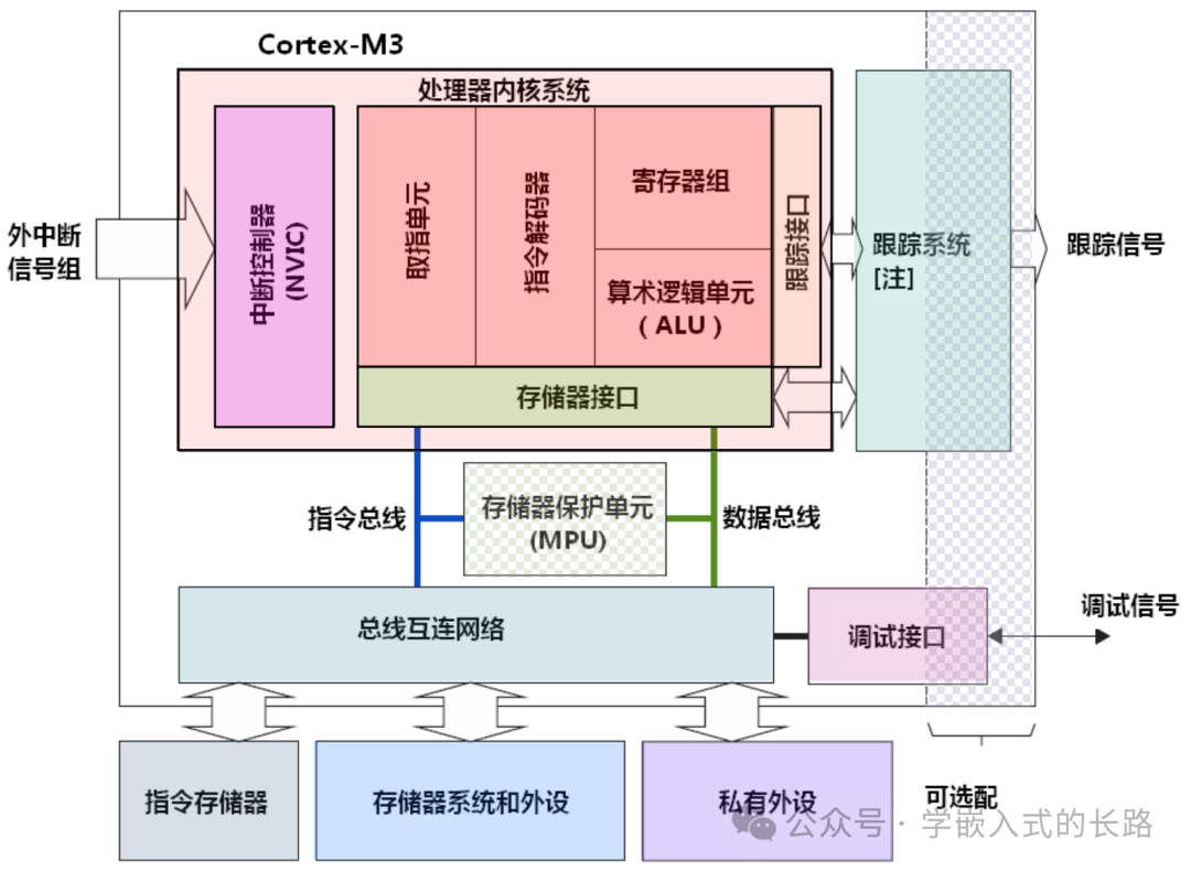
Register Set
The Cortex-M3 processor has a register set from R0 to R15. Among them, R13 serves as the stack pointer (SP). There are two SPs, but only one can be visible at a time, which is known as a “banked” register.
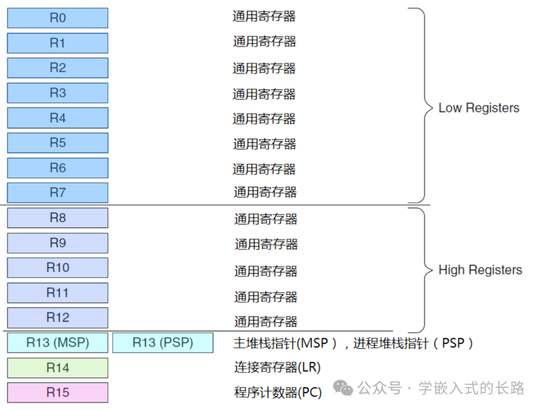
R0-R12: General Purpose Registers
R0-R12 are all 32-bit general-purpose registers used for data operations. However, note that most 16-bit Thumb instructions can only access R0-R7, while 32-bit Thumb-2 instructions can access all registers.
Banked R13: Two Stack Pointers
The Cortex-M3 has two stack pointers, but they are banked, so only one can be used at any given time.
- • Main Stack Pointer (MSP): The default stack pointer used after reset, for the operating system kernel and exception handling routines (including interrupt service routines).
- • Process Stack Pointer (PSP): Used by user application code. The lowest two bits of the stack pointer are always 0, meaning the stack is always 4-byte aligned.
R14: Link Register
When calling a subroutine, the return address is stored in R14.
R15: Program Counter Register
Points to the current program address. Modifying its value can change the execution flow of the program.
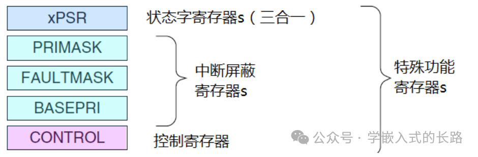
Special Function Registers
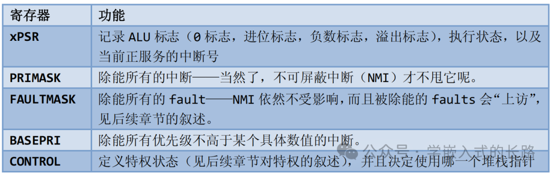
The Cortex-M3 also features several special function registers at the core level, including:
- • Program Status Register (PSRs)
- • Interrupt Mask Registers (PRIMASK, FAULTMASK, BASEPRI)
- • Control Register (CONTROL)
Operating Modes and Privilege Levels
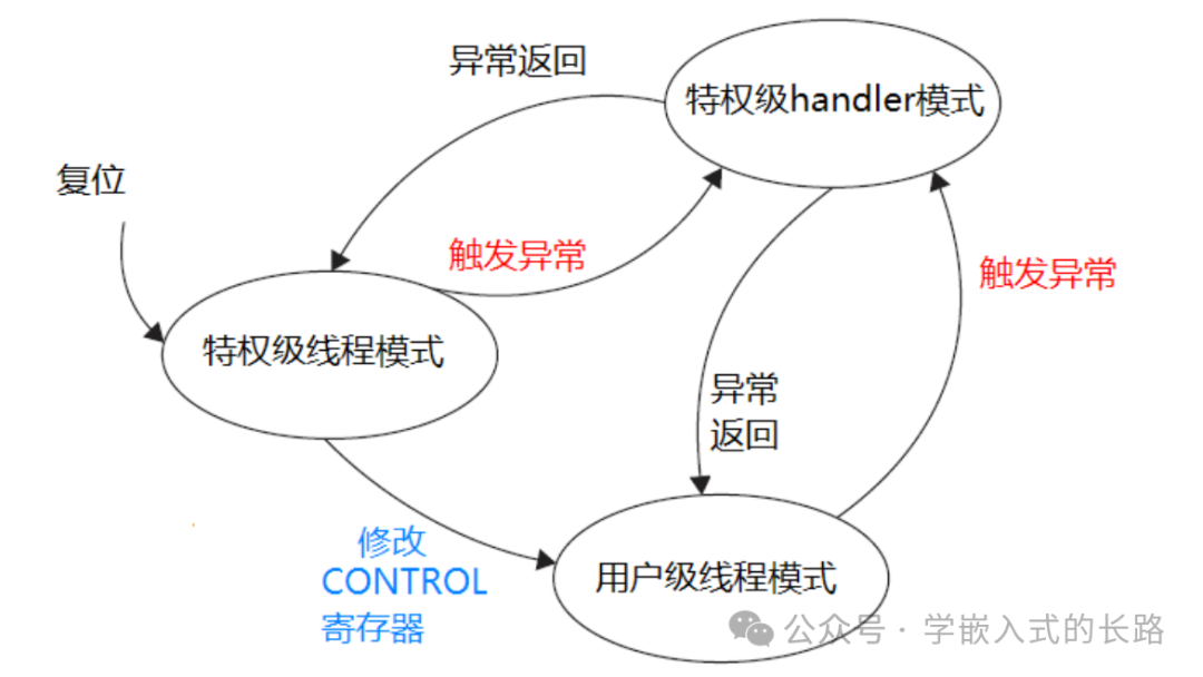
The Cortex-M3 processor supports two operating modes and two privilege levels. The two operating modes are: Handler mode and Thread mode. The purpose of introducing these two modes is to distinguish between the code of ordinary applications and the code of exception service routines, including interrupt service routines.Another aspect of the Cortex-M3 is the hierarchy of privileges—privileged and unprivileged. This provides a memory access protection mechanism, preventing ordinary user program code from accidentally or maliciously executing critical operations. The processor supports two privilege levels, which is a fundamental security model.

When the CM3 runs the main application (Thread mode), it can use either privileged or unprivileged levels; however, exception service routines must execute at the privileged level. After reset, the processor defaults to Thread mode with privileged access. In privileged mode, the program can access all ranges of memory (if there is an MPU, it must also stay outside the areas defined by the MPU) and can execute all instructions.
Nested Vectored Interrupt Controller
The Cortex-M3 features an interrupt controller at the core level—Nested Vectored Interrupt Controller (NVIC). It has a close “intimate contact” with the core—tightly coupled with it.NVIC provides the following functionalities:
- • Support for Nested Interrupts: When an exception occurs, the hardware automatically compares the priority of that exception with the current exception’s priority. If a higher priority exception arrives, the processor interrupts the current interrupt service routine (or normal program) to service the new exception—this is immediate preemption.
- • Support for Vector Interrupts: When responding to an interrupt, the CM3 automatically locates a vector table and finds the entry address of the ISR based on the interrupt number, then jumps to execute it.
- • Support for Dynamic Priority Adjustment: Software can change the priority of interrupts at runtime. If the priority of the corresponding interrupt is modified within an ISR, and that interrupt has a new instance pending, it will not interrupt itself, thus avoiding reentry risks.
- • Significantly Reduced Interrupt Latency: The Cortex-M3 introduces several new features to shorten interrupt latency, including automatic context saving and restoration, as well as other measures to reduce ISR inter-latency during interrupt nesting.
- • Interrupt Masking: Interrupts/exceptions below a certain priority threshold can be masked (set BASEPRI register), or all can be masked (set PRIMASK and FAULTMASK registers).
Memory Mapping
The Cortex-M3 supports 4GB of memory space, divided into several regions:
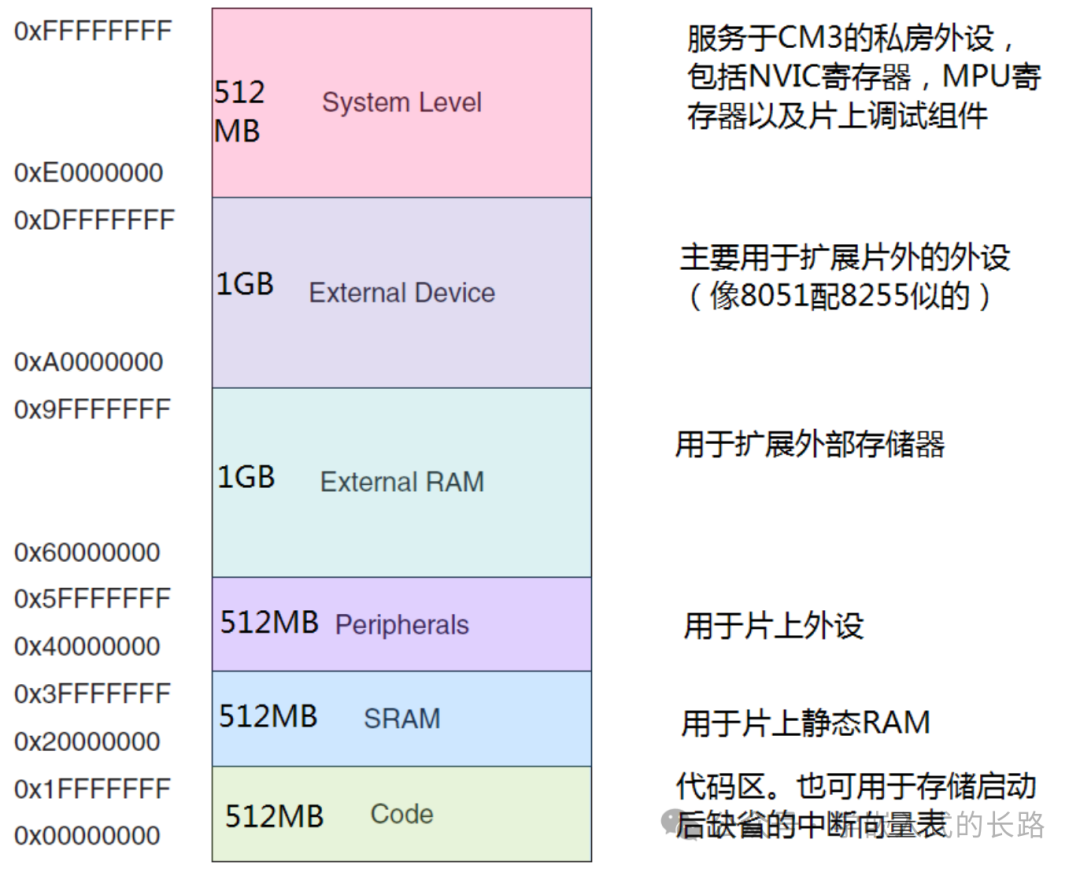
The Cortex-M3 has predefined a “coarse” memory mapping. By mapping the registers of on-chip peripherals to the peripheral area, these peripheral registers can be accessed simply as if accessing memory, thus controlling the operation of the peripherals.
Bus Interfaces
The Cortex-M3 has several bus interfaces to allow CM3 to address and access memory simultaneously. They are:
- • Two Instruction Storage Area Buses: I-Code bus and D-Code bus. The former is used for instruction fetching, while the latter is used for table lookups and other operations, optimized for best execution speed.
- • System Bus: Used to access memory and peripherals, covering areas including SRAM, on-chip peripherals, off-chip RAM, off-chip expansion devices, and part of the system-level storage area.
- • Private Peripheral Bus: Responsible for accessing some private peripherals, mainly for accessing debugging components. They are also in the system-level storage area.
Memory Protection Unit (MPU)
The Cortex-M3 has an optional Memory Protection Unit. With it, different access restrictions can be applied to privileged and unprivileged accesses. When a violation is detected, the MPU generates a fault exception, which can be analyzed by the fault exception service routine and corrected if possible.
Interrupts and Exceptions
All interrupt mechanisms of the CM3 are implemented by the NVIC. In addition to supporting 240 interrupts, the NVIC also supports 16-4-1=11 internal exception sources, enabling fault management mechanisms. As a result, the CM3 has 256 predefined exception types:
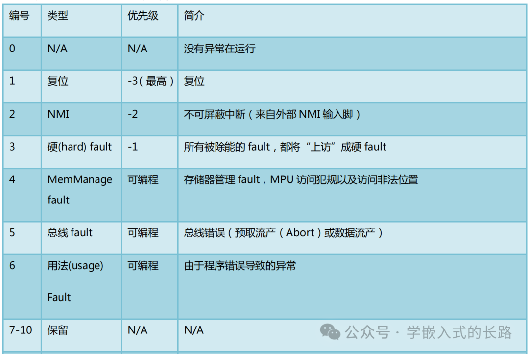
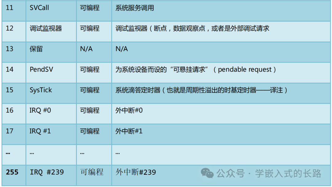
Although the CM3 supports 240 external interrupts, the specific number used is determined by the chip manufacturer. The CM3 also has an NMI (Non-Maskable Interrupt) input pin. When asserted, the NMI service routine will execute unconditionally.
To be continued…