In the field of explosion and shock wave testing, pressure measurement has always been a core challenge. Although traditional piezoelectric pressure sensors are widely used, they face limitations such as insufficient response frequency, complex calibration requirements, and susceptibility to electromagnetic interference. These limitations become particularly pronounced in extreme environments with strong electromagnetic radiation and high temperatures.In recent years, a novel thin-film pressure measurement method has been proposed, which abandons the traditional pressure-deformation relationship and instead utilizes the direct proportional relationship between pressure and film acceleration, providing a new approach for shock wave pressure measurement..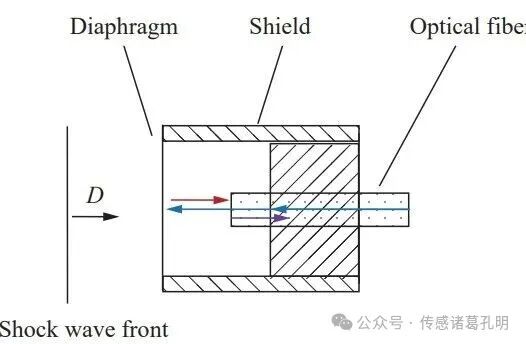 The Principle of Thin-Film Pressure Sensors
(If you are interested in this article and want to learn more about the technical details or need the original text, please contact the author for communication.)
1. The Dilemma: Measurement Bottlenecks of Piezoelectric Sensors
In shock wave pressure measurement, piezoelectric pressure sensors are widely used due to their advantages in response frequency, measurement range, and sensitivity. Researchers such as Yu Jianliang, Hu Hongwei, and Huang Ju have utilized these sensors for measuring explosion shock wave pressures.
The response frequency of these sensors can reach up to 300 kHz, with a maximum pressure measurement limit of 200 MPa, making their performance impressive. However, even with a response frequency of approximately 300 kHz, it still cannot fully meet the stringent requirements for measuring explosion shock wave pressures, necessitating the use of dynamic compensation techniques to improve testing accuracy.
Another major issue with piezoelectric sensors is their complex calibration. Due to the use of piezoelectric materials as sensitive elements, the charges generated under pressure are prone to leakage, thus requiring quasi-static or dynamic calibration methods to determine their sensitivity coefficients.
This calibration process is not only complex but also prone to introducing new errors, affecting measurement accuracy. Additionally, piezoelectric pressure sensors are sensitive to environmental temperature and electromagnetic interference, challenging their reliability in complex scenarios.
2. Innovative Breakthrough: The Principle of Thin-Film Pressure Measurement
To meet the demand for large-range dynamic pressure measurements in extreme environments, Wang Zhao and others from the Northwest Institute of Nuclear Technology proposed a novel thin-film pressure measurement method specifically designed to capture the reflected overpressure peak of shock waves in the air.
Unlike conventional sensing technologies, this innovative method is based on a simple physical principle — the direct proportional relationship between the pressure to be measured and the film acceleration.
The core of the thin-film pressure sensor is a circular film fixed at the end face of a cylindrical sleeve. When a shock wave acts on the film, the film will move. According to Newton’s second law, the force acting on the center region of the film equals the product of its acceleration and mass, allowing the shock wave pressure to be calculated.
As the film’s speed of movement increases under pressure, the pressure acting on the film decreases. Therefore, this sensor is primarily used to obtain the reflected pressure peak of shock waves rather than the complete pressure history. It is noteworthy that this sensor is generally used in cases of normal reflection of shock waves, as oblique incidence can affect measurement accuracy.
3. Key Parameters: Scientific Considerations in Film Design
Many factors influence thin-film pressure measurement, including film thickness, pressure to be measured, data processing methods, film uniformity, and film defects. Researchers typically select industrial stainless steel films as sensitive elements, and with improvements in machining precision, the uniformity and defects of stainless steel films have been effectively controlled.
The sensitive film starts moving from rest under the action of shock wave pressure, and the moving film will inevitably be affected by air resistance, which also leads to a reduction in reflected pressure (compared to the reflected pressure generated when the shock wave acts on a solid wall). These factors will all affect the final pressure measurement results.
The speed of the film’s movement is mainly related to the film thickness, the pressure to be measured, and the duration of action, making it quite complex to describe the process of the film under shock using theoretical models.
Moreover, the film will inevitably be affected by edge disturbances and supports, and the time required for this disturbance to propagate to the center region of the film is known as the effective measurement duration of the film. The effective duration is proportional to the radius of the film, and within this effective duration, the influence of edge disturbances on the acceleration of the center region can be neglected.
When the radius of the stainless steel film is 8 mm, the effective duration is approximately 2.5 μs. All discussions regarding the thin-film pressure sensor are conducted within this effective measurement duration.
4. Simulation and Exploration: A Scientific Journey to Optimal Parameters
To systematically analyze the impact of film thickness and pressure to be measured on pressure measurement, researchers used commercial finite element simulation software to conduct numerical simulations, obtaining motion parameter data for stainless steel films of different thicknesses under various pressure conditions.
The pressure curve of explosion shock waves has a steep rise, reaching the nanosecond level. For the microsecond effective measurement time of the thin-film pressure sensor, the rising process of pressure can be neglected, and it can be approximated that the pressure is a sudden change.
The falling edge of explosion shock wave pressure generally decreases exponentially, with significant duration differences, typically lasting hundreds of microseconds or more. Rapid falling edges can affect the measurement accuracy of thin-film pressure sensors, so the research team employed both step-shaped shock waves and explosion shock waves to quantify the impact of pressure decline on pressure measurement.
Within the effective duration, the edge disturbances and supports have not yet acted on the center region of the film. To obtain the motion history of the center region of the film under the action of shock waves, a one-dimensional model can be selected for numerical simulation to reduce computational load.
Step-Shaped Shock Wave Loadingsimulation used an axisymmetric finite element model, with a model length of 100 mm and a radius of 10 mm. Researchers modified the initial density and internal energy of some air materials to form a high-pressure zone, thus generating a step-shaped shock wave.
 Step Pressure Generation Model
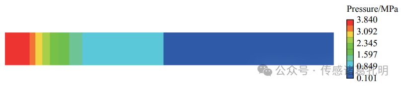 Cloud Map of Step Pressure at a Certain Moment
By adjusting the initial density and internal energy of the high-pressure air material, researchers obtained various incident pressure conditions. By constraining the motion speed of the stainless steel mesh to zero, standard reflected pressure can be obtained; by not constraining the motion state of the film mesh, the motion parameter history of stainless steel films of different thicknesses under step pressure can be obtained.
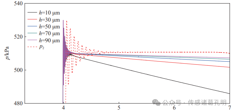
Under 0.239 2 MPa incident pressure, surface pressure of films of different thicknesses
Explosion Shock Wave Loadingsimulation targets the parameters of shock waves generated during chemical explosions, impacts, etc., which are not step-shaped but exhibit rapid rise and exponential decay characteristics. Researchers simulated the scenario of air shock waves generated by a small amount of explosives detonating at close range acting on the film, establishing a two-dimensional axisymmetric finite element model.
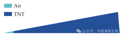 Explosion Shock Wave Generation Model
By obtaining the incident pressure and standard reflected pressure of the shock wave at a specific detonation distance, as well as the motion parameter history of different thickness films under explosion shock wave pressure, researchers laid a solid foundation for subsequent data analysis.
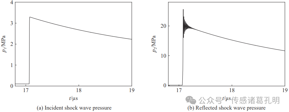
Incident shock wave pressure and reflected shock wave pressure at a 54 mm detonation distance
5. Data Analysis: Precise Calculation from Speed to Pressure
The numerical simulation obtained the motion speed of the film under shock wave pressure in various working conditions, which can further obtain acceleration. Combined with the surface density data of the film, the pressure acting on the film can be calculated. By comparing the calculated pressure with the known standard reflected pressure in the numerical simulation, the advantages and disadvantages of the thin-film pressure measurement under that working condition can be evaluated.
In the thin-film pressure measurement method, researchers used a fiber optic F-P interferometer to obtain the motion parameters of the film. Affected by the measurement accuracy of interference and the effective measurement duration, it is necessary to use microsecond-level film displacement (or speed) data to obtain the acceleration at the moment of shock initiation, thereby estimating the peak value of the shock wave reflected pressure.
From the pressure change curve on the surface of the film under shock, it can be seen that the pressure on the film surface gradually decreases, and the thinner the film, the greater the decline. The reason for this phenomenon is that under the action of shock wave pressure, the film starts to accelerate from rest, and as the film speed increases, the film’s reflection effect on the incident pressure weakens, leading to a pressure drop.
As the pressure drops, the acceleration also decreases. If the film speed data is used for linear fitting to obtain acceleration, it is equivalent to obtaining the average value of acceleration data within the fitting duration, which will reduce the pressure measurement accuracy.
To address this issue, the research team proposed using quadratic or higher-order polynomials for speed fitting, and then differentiating the fitted polynomial to obtain the acceleration at the moment of shock initiation, thus compensating for the impact of pressure decline on measurement.
Taking the motion speed curve of a 30 μm thick stainless steel film under a step pressure of 78.05 MPa as an example, researchers obtained fitting parameters for different fitting durations, different fitting orders, and different fitting starting moments based on speed data, and then estimated pressure data and calculated the relative error compared to the standard pressure.
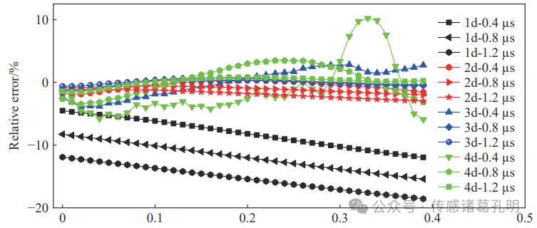
Relative error of pressure obtained from speed data fitting under a step pressure of 78.05 MPa for different thickness films
Similarly, researchers also obtained the relative error of pressure obtained from speed data fitting under a step pressure of 4.619 MPa and under an explosion shock wave with a peak value of 20.10 MPa for different thickness films.
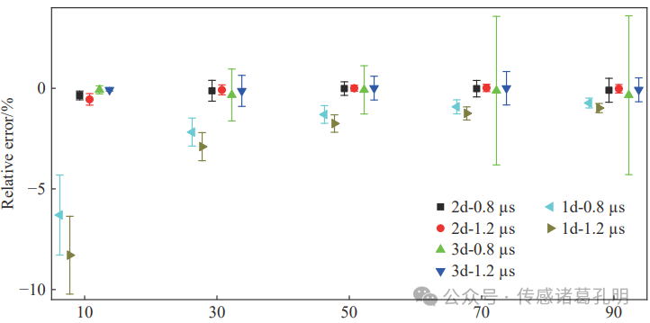
Relative error of pressure obtained from speed data fitting under a step pressure of 4.619 MPa for different thickness films
By summarizing the fitting analysis of speed data, researchers obtained optimal values for parameters such as stainless steel film thickness, fitting starting moment range, fitting order, and fitting duration under different pressure conditions, as well as the relative error of pressure obtained from fitting compared to standard pressure.
6. Experimental Verification: A Perfect Combination of Theory and Practice
At the bottom end face of the shock wave tube, researchers arranged thin-film fiber optic pressure sensors of different thicknesses and standard piezoresistive pressure sensors to verify some conclusions from the numerical simulation analysis. The shock wave generated by the shock wave tube is considered an ideal step pressure signal, with a rise time reaching the nanosecond level, and the duration of the step platform generally exceeding the millisecond level.
In the experiment, the response times of both types of pressure sensors were much greater than the rise time of the shock wave tube pressure, so the outputs of both pressure sensors were step responses.
In one experiment, researchers obtained the original interference signals of the 10 and 50 μm thick thin-film fiber optic pressure sensors, as well as the output pressure signals from the piezoresistive pressure sensors. From the signals of the piezoresistive pressure sensor, oscillation and overshoot phenomena can be observed, which are typical responses of piezoresistive pressure sensors (whose mechanical model is generally a single-degree-of-freedom second-order system) under step pressure.
To accurately determine the platform pressure of the shock wave tube, researchers used the mean value of the stable data segment (200-500 μs) as the reference pressure, approximately 0.9460 MPa.
After obtaining the peak value of the fiber optic interference signal using peak recognition methods, researchers derived the displacement data of the film from the peak data based on the theory of dual-beam interference. Furthermore, they conducted quadratic polynomial fitting of the displacement data (equivalent to linear fitting of speed data).
Using quadratic polynomial fitting of displacement data, researchers estimated the accelerations of the 10 and 50 μm thick films, and combined with the measured surface density of the films, calculated the corresponding reflected overpressure using the thin-film pressure calculation formula. Knowing the reference pressure of 0.9460 MPa, the relative errors of the pressures obtained from quadratic fitting were -4.48% and -2.77%, respectively.
Similarly, after conducting cubic polynomial fitting of the displacement data, the estimated pressures relative to the reference pressure had relative errors of -1.78% and -2.75%, respectively.
Quadratic and cubic polynomial fitting of the film displacement data yielded four pressure values, with the pressure value obtained from quadratic fitting of the 10 μm film displacement data being the smallest, while the other three fitting results were similar, with the maximum relative error being 1.02%.
This phenomenon indicates that when the film thickness is small, the high speed of the film leads to a decrease in pressure reflection effect and increased air resistance, resulting in larger errors in quadratic fitting of displacement data. Cubic fitting or using thicker films can be employed to obtain pressure, which aligns with the conclusions obtained from numerical simulations.
7. Future Prospects: Application Prospects of Thin-Film Pressure Sensors
Through systematic numerical simulations and experimental verifications, researchers obtained optimal parameters for thin-film pressure sensors: stainless steel film thickness of 50-70 μm; speed data fitting as a quadratic polynomial (linear fitting when the pressure to be measured is less than 1 MPa); fitting duration of approximately 0.8 μs.
Theoretically, for reflected pressures of 5 MPa and below, the relative measurement error can be controlled within 1%; for reflected pressures ranging from 5 MPa to 1 GPa, the relative measurement error can be controlled within 3%. This level of accuracy is considered advanced in the field of shock wave pressure measurement, giving thin-film pressure sensors a promising application prospect.
This new type of sensor has advantages such as no calibration required, simple manufacturing, low cost, and high measurement accuracy, making it particularly suitable for large-range dynamic pressure measurements in extreme environments with strong electromagnetic radiation and high temperatures. Although the film in the sensor may deform or be damaged under shock wave action, leading to non-reusability, the low cost of the film and the simplicity of pressure probe assembly without calibration still provide high application value for this sensor.
The successful development of the thin-film pressure sensor not only provides a new technical means for shock wave pressure measurement but also demonstrates the powerful capability of a simple physical principle based on first principles (Newton’s second law) in solving complex measurement problems.
From exploring basic principles to parameter optimization, from numerical simulations to experimental verifications, the development process of this new type of sensor reflects the importance of interdisciplinary integration in modern scientific research and provides a reference for the development of other types of sensors.
Friends in need of pressure sensors are welcome to contact Teacher Kong Ming for the most reasonable suggestions. The content of this article is organized from “Explosions and Shock Waves” Issue 7 “Parameter Design of New Thin-Film Pressure Sensors”.
Follow me for more insights into cutting-edge sensor technologies!