In industrial control, many devices have a certain sequence of actions, such as the handling of objects by robotic arms, sorting and packaging of workpieces on assembly lines, and process control on installation machinery. These actions are carried out step by step, and their workflow diagrams can be easily drawn. The automatic processing of workpieces by combined machine tools also falls into this category.
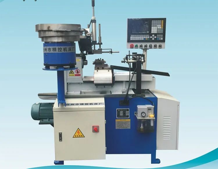
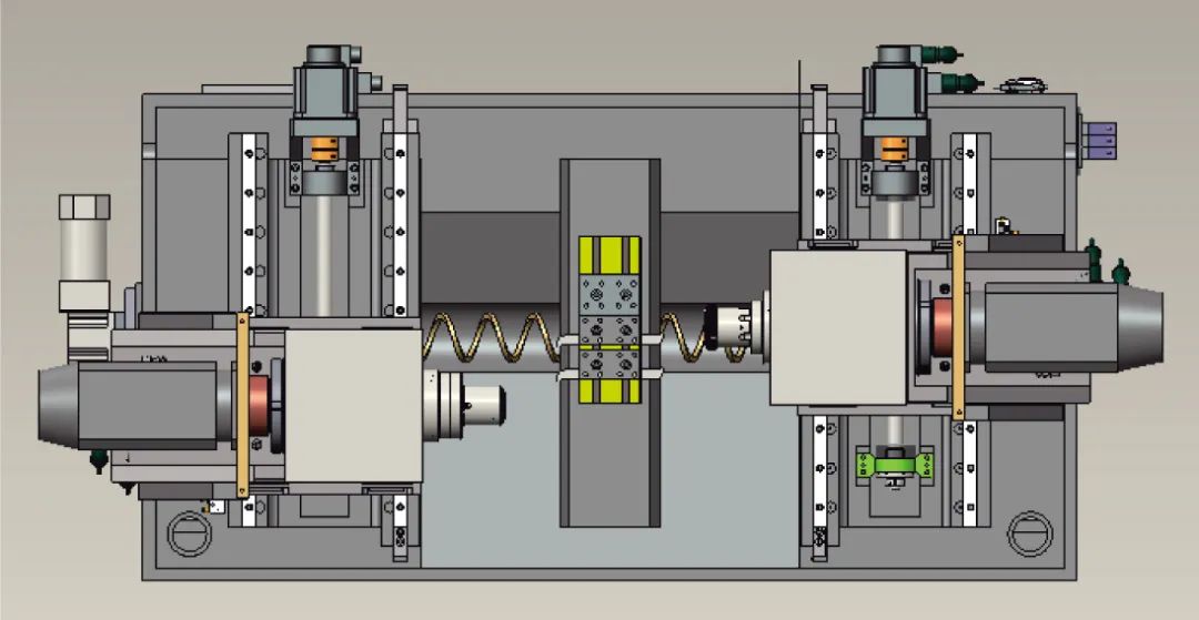
Combined machine tools can usually complete workpiece processing automatically, with a high degree of automation and production efficiency. The motion control system of the combined machine tool spindle is driven by hydraulics. Its working principle is as follows: one solenoid valve controls the spindle’s direction of movement; when powered, the spindle moves forward, and when not powered, it moves backward; another solenoid valve controls the spindle’s speed; when powered, the spindle moves quickly, and when not powered, it moves slowly.
The working process is as follows: the work table starts at the left side, with limit switch SQ1 ON. After pressing the start button SBO, it first moves quickly until reaching limit switch SQ2, at which point SQ2 is ON, and it switches to slow forward movement (working state), starting to process the workpiece. When processing reaches limit switch SQ3 which is ON, it switches to fast retreat, retreating quickly until limit switch SQ2 is ON, then it moves forward quickly again until limit switch SQ3 is ON, then switches to slow forward movement (working state), processing until the specified size, at which point SQ4 is ON, and it retreats back to the original position, stopping when limit switch SQ1 is ON, completing one working cycle.
According to the above requirements, except for the initial state, the working process can be divided into six sequential working states: from the original position → fast forward to SQ2 → work forward to SQ3 → fast retreat to SQ2 → fast forward to SQ3 → work forward to SQ4 → fast retreat back to the original position SQ1. The above sequential working process can be represented by working states, detailing each state’s tasks, transition conditions, and transition directions.(1) Initial state: The spindle is at the origin position. When the start button is pressed and limit switch SQ1 is ON, it transitions from the initial state to working state 1.(2) Working state 1: Fast forward to SQ2; when SQ2 is ON, the working state transitions to working state 2.(3) Working state 2: Work forward to SQ3; when SQ3 is ON, the working state transitions to working state 3.(4) Working state 3: Fast retreat to SQ2; when SQ2 is ON, the working state transitions to working state 4.
 (5) Working state 4: Fast forward to SQ3 again; when SQ3 is ON, the working state transitions to working state 5.(6) Working state 5: Continue to work forward to SQ4; when SQ4 is ON, the working state transitions to working state 6.
(7) Working state 6: Fast retreat back to original position SQ1; when SQ1 is ON, the working state returns to the initial state.
From the above analysis, it can be seen that by decomposing complex control tasks into several working states, we can obtain the working state diagram for the motion control of the combined machine tool spindle.
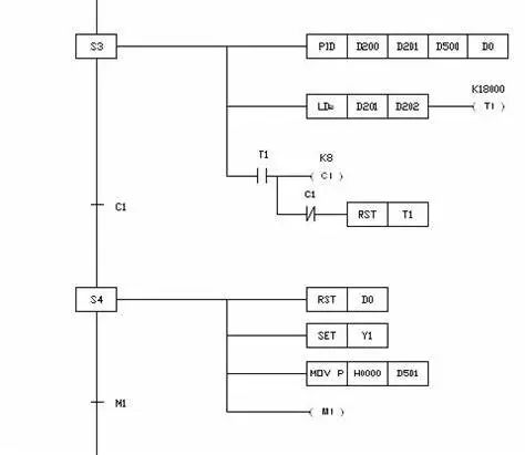
State Transition DiagramThe state transition diagram (SFC), also known as the sequential function chart, is a graphical programming language that decomposes complex tasks or working processes into several procedures (or states), reflecting the transition conditions and directions of the procedures (or states). It combines the intuitive nature of process flow diagrams with the advantages of decomposing and integrating complex control logic relationships.
The state transition diagram expresses control intentions, breaking down a complex sequential control process into several states, each with different actions, separated by transition conditions that do not affect each other. When the conditions between two adjacent states are met, a transition occurs, meaning the action above ends and the next state begins.
The state transition diagram does not involve the specific technology of the control functions described but serves as a universal technical language for further design and technical communication among professionals in different fields. Most PLC products now have specific instructions and components designed for programming with state transition diagrams, making them very convenient to use.
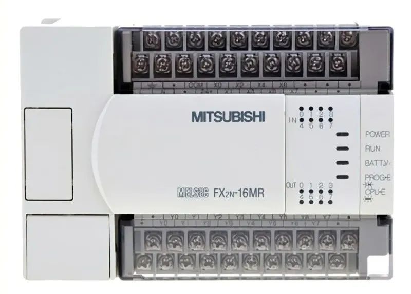
State Relay SIn the state programming method, state elements are typically used to represent the procedures (or states) of the system. In the FX3U and FX2N series PLCs, there are dedicated soft element state relays S, where the allocation range for the state relay S in the FX3U series PLC is S0 to S4095, totaling 4096 points. The allocation range for the state relay S in the FX2N series PLC is:
S0 to S999, totaling 1000 points.S0~S9: Initial state.S10 to S19: Zero return state, used for returning to the origin in multi-operation mode control.S20 to S499: General state relays, used for intermediate states in the state transition diagram.S500 to S899: Holding state relays, which have a power-off holding effect, used for states that need to be maintained during power outages.
This range can be set as general state relays through parameters.S5900 to S999: Alarm-specific state relays, used as alarm components.S1000 to S4095: Holding state relays, exclusive to the FX3U series PLC.The dynamic make and break contacts of each state element can be used freely within the PLC, with no limit on the number of uses, and they can also be used as auxiliary relays.