Introduction
While preparing the content for the birthday song player, I had already read most of Exploring Arduino. After that, I began looking for other project topics.
However, once I left the guidance of the book, the DIY project production cycle became longer. Completing the design, ordering parts, and assembling took over a week, and the things I designed did not always pass on the first try, often requiring multiple iterations to achieve the desired effect.
Before completing those new projects, I planned to continue writing tweets around the content of Exploring Arduino.
In this unit, the book mainly introduces the Serial Peripheral Interface (SPI) communication protocol from a hardware perspective, demonstrating how to call SPI communication in the program through the example of an electronic potentiometer chip.
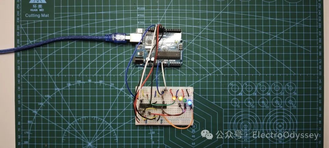
The electronic potentiometer can act as a variable resistor in the circuit, controlling the brightness of an LED. After importing the program into the development board, the four LEDs on the breadboard will gradually increase in brightness, wait a few seconds at maximum brightness, and then gradually dim.
Experimental Materials
1 Computer
1 USB-A to USB-B Data Cable
1 Arduino UNO
1 Breadboard
1 MCP4231 SPI Electronic Potentiometer
4 100 Ohm Resistors
1 150 Ohm Resistor
1 Red LED
1 Yellow LED
1 Green LED
1 Blue LED
Several Jumper Wires
Theoretical Preparation – Hardware Part
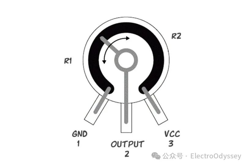
The electronic potentiometer functions to adjust the current in the circuit. Through SPI communication, the development board can set the resistance value of the potentiometer to increase or decrease the brightness of the LED.
To understand how to use the electronic potentiometer, we need to refer to its data sheet. Searching online for the potentiometer model “MCP4231” will yield this document.
This image in the data sheet tells us which pins are the output pins of the potentiometer chip and which pins control the potentiometer.
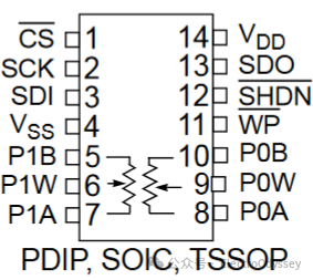
The pins of the chip are numbered in a counter-clockwise order, starting from the top left corner to the top right corner. The two potentiometer symbols at the bottom of the image indicate that there are two independently controllable potentiometers in this chip.
The P0B, P0W, P0A at the bottom right corner are the three pins of the first potentiometer; the P1B, P1W, P1A at the bottom left corner are the three pins of the second potentiometer.
The three pins responsible for SPI communication are the Serial Clock (SCK), Master Out Slave In (MOSI/SDI), and Master In Slave Out (MISO/SDO), which are pins 2, 3, and 13 respectively.
The Vdd at the top right corner is the power pin, and the Vss in the middle left is the ground pin. The CS in the top left corner corresponds to the chip select signal, and the horizontal line above the label indicates that to select this chip, that pin needs to be pulled low.
The SHDN pin on pin 12 is used to turn the entire potentiometer on or off. Bringing this pin to a low state can turn off the potentiometer.
The WP pin on pin 13 represents write protection. However, this chip’s WP pin is floating and not connected to the internal circuit.
Knowing the functions of these pins, we can connect the two chips to the development board as required.
Among them, the SCK, SDI, and SDO of the two potentiometers will be connected to the development board through the same three wires. Along with the two jumper wires for the chip select, a total of five wires are responsible for SPI communication, connected to ports 9-13.
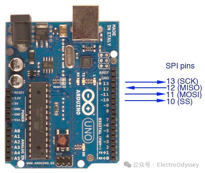
The Arduino IDE has a built-in SPI communication library that can call functions to send information to the slave device. By default, every development board connects to fixed SCK, SDI (MOSI), and SDO (MISO) ports.
In this experiment, the Arduino Uno development board connects SCK to pin 13, MISO to pin 12, and MOSI to pin 11.
The next section is the DC/AC characteristics of the components. The Wiper Resistance section at the bottom left shows the built-in resistance of the potentiometer, which ranges between 70 Ohm and 160 Ohm.
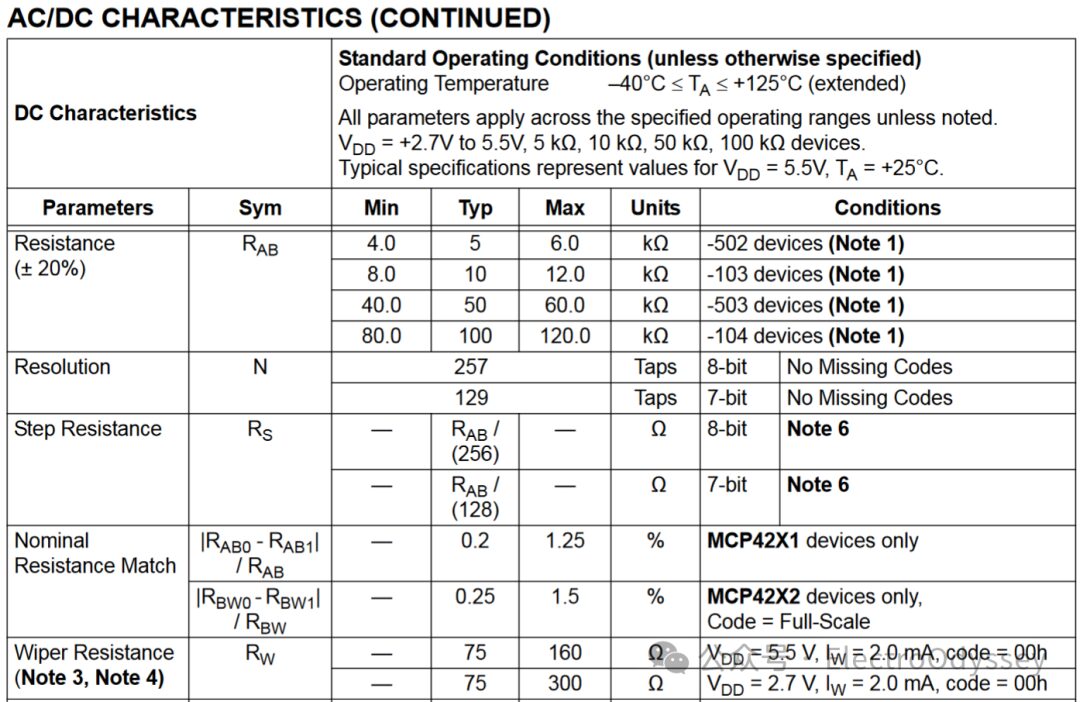
When selecting the current-limiting resistor, we also need to consider the internal resistance of the chip.
To keep the current through the LED below 20mA, we need a current-limiting resistor of more than 150 Ohms. Subtracting the 70 Ohms of the potentiometer gives us a limit of more than 80 Ohms. The book here chooses a 100 Ohm current-limiting resistor, meaning the total resistance in the circuit will be between 170-260 Ohms.
The resistance column in the upper half of the table is marked with an error of ±20%, which is greater than the error of ordinary potentiometers or most color ring resistors. This means that this electronic potentiometer is not suitable for experiments requiring high precision, but it is sufficient for controlling the brightness of the LED in this project.
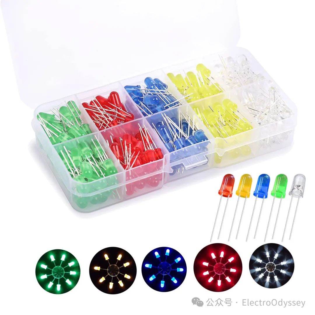
The output devices of this small device are four LEDs: red, yellow, blue, and green. The first LED was born in 1927, and it has not yet reached 100 years. In 1968, the LED was first used in a display by HP, taking its first step towards commercialization.
However, for a long time, LEDs could not be used for lighting due to their limited brightness and could only be installed in various devices as indicator lights. Additionally, the efficiency of blue LEDs at that time was very low, making it impossible to mix the three primary colors to produce white light.
It was not until 1993 that three Japanese scientists produced efficient blue LEDs.

This invention promoted the development of white LEDs and improved the lighting efficiency of artificial light sources. In 2014, these three scientists were awarded the Nobel Prize in Physics.
Theoretical Preparation – Software Part
The previously introduced I2C communication protocol requires one clock line and one bidirectional data line. In this chapter, the SPI communication protocol uses two unidirectional data lines, one for sending and one for receiving data.
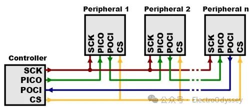
Additionally, each slave device is connected to the master device through a Chip Select (CS) line, allowing the master device to select the communication target.
While more data lines increase the hardware complexity of SPI devices, the SPI protocol offers higher transmission speeds, allowing the master and slave devices to exchange more information simultaneously.
Like I2C, Arduino also has a built-in SPI communication library. When sending information, I need to set the chip select port of an electronic potentiometer to low to select that device, and then call the SPI.transfer() function to sequentially send the 8-bit potentiometer number and 8-bit set value.
After completing the setup, I then set the chip select line to high to end the communication.
The book’s author also used two for loops to adjust the values of the electronic potentiometer between 0-128, allowing the four LEDs connected to the chip to achieve a gradual brightening and dimming effect.
In addition to electronic potentiometers, many sensors also support the SPI communication protocol. The nRF24L01 wireless module, which was tried in the previous remote assistance project, also uses SPI communication.
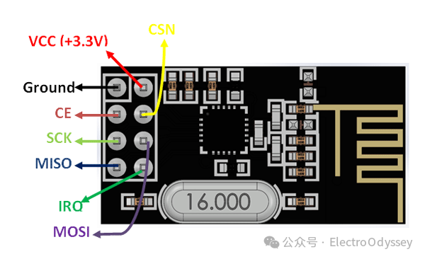
There seem to be many interfaces
At that time, SPI communication required four wires, plus the power and ground wires and data lines, totaling seven wires, which made connecting the wires correctly quite confusing for me. This is also a problem with the SPI communication protocol—its wiring is too complex.
Experimental Process
After assembling the components according to the book’s illustration, I entered the code into the software and connected the device for debugging. During the trial, I found that the blue LED was the most efficient, appearing very bright among the four LEDs.
To balance the brightness of the four LEDs and make the overall lighting more coordinated, I changed the resistor in the blue LED circuit from 100 Ohm to 150 Ohm to reduce the current flowing through the blue LED. After the adjustment, the brightness of the blue LED was slightly lower than before.
Previously, I had also tried using Pulse Width Modulation (PWM) to control the brightness of the LEDs. PWM controls the brightness by changing the duty cycle of the 5V pulse, making the LEDs flicker quickly, which makes them appear dimmer.
Its advantage is the ability to completely turn off the LED lights, allowing them to transition between bright and off; however, the problem is that only six of the fourteen digital output ports on the development board have PWM functionality, and each port can provide a maximum current of 40mA.
In contrast, while the electronic potentiometer can only switch the LEDs between dim and full brightness, it has no current limit, theoretically allowing up to 70mA of current to pass at 5V voltage.
Additionally, since the electronic potentiometer can change resistance rather than duty cycle, it can adjust the volume of the input sound signal. PWM cannot achieve this because it alters the signal content.
Results Display
One More Thing
Seeing this part of the book was a month ago, which caused my impression of the code not to be as deep as when I wrote the tweets.
However, once I jumped out of the code, I could shift my focus to other less noticeable things, such as the LED mentioned this time.
References
Blum, J. (2013). Exploring Arduino: Tools and techniques for engineering wizardry. Wiley.