1 Introduction
Using Electronic Design Automation (EDA) software to design electronic circuits is the mainstream method in today’s electronic design. Currently, commonly used EDA tools in China include Multisim, Protel, Matlab, Spice, Maxplus II, etc. Among these, Protel 99 SE is a circuit design software that runs in a Windows environment, mainly consisting of schematic design, PCB design, PLD (Programmable Logic Device) design, and circuit simulation components. Multisim 8, on the other hand, is a software specifically for circuit simulation and design, featuring ease of learning, a user-friendly interface, and powerful simulation capabilities.
Based on the analysis of the simulation functions of Multisim 8 and the printed circuit board design capabilities of Protel 99 SE, a method for electronic product design that combines Multisim 8 and Protel 99 SE is proposed. This method first uses Multisim 8 to design the circuit schematic, simulate and debug it, and generate a netlist file. Then, Protel 99 SE is used to call the netlist file and make the necessary modifications, followed by PCB design.
2 Multisim 8 and Protel 99 SE
Multisim 8’s simulation analysis includes 19 types of simulation analysis methods, powerful virtual instruments, and a vast library of simulation components, allowing for the design and simulation of various electronic circuits, including analog circuits, digital circuits, relay circuits, and PLC (Programmable Logic Controller) control circuits.
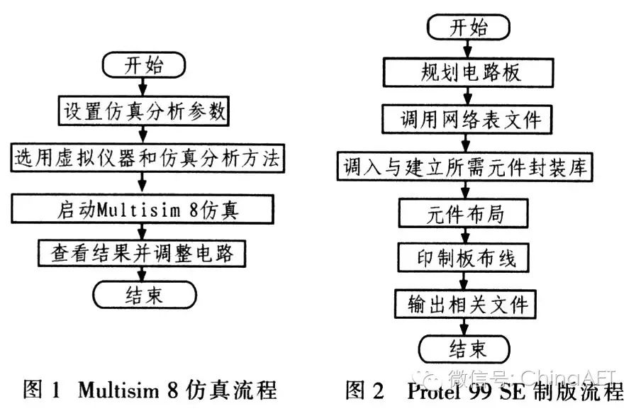
Multisim 8 provides multiple circuit simulation engines, including Xspice, VHDL, Verilog, and a combination of these three simulation engines. For circuits suitable for PCB production, the Xspice simulation engine is preferred, while complex digital circuits generally use the VHDL and Verilog simulation engines. Multisim 8 includes circuit analysis methods such as DC operating point analysis, transient analysis, Fourier analysis, noise analysis, distortion analysis, sensitivity analysis, temperature sweep analysis, Monte Carlo analysis, and transfer function analysis, which help designers analyze circuit performance. It also offers a comprehensive range of virtual test instruments to assist designers in understanding circuit operation states and results. The main instruments include commonly used digital multimeters, signal generators, dual-channel oscilloscopes, DC power supplies, and less common instruments such as Bode plotters, word signal generators, logic analyzers, logic converters, distortion measurement instruments, spectrum analyzers, and network analyzers. Additionally, Multisim 8 provides a large component library and a powerful component editor, allowing users to modify parameters of components in the Master library or create new component models. The components offered by Multisim 8 are divided into virtual components and actual components, with virtual components being non-standardized and their parameters freely set, while actual components conform to real standards. The steps for conducting simulation analysis in Multisim 8 are shown in Figure 1, while Figure 2 illustrates the main process of PCB design in Protel 99 SE.
3 Application Example
This section introduces the basic process and methods of using Protel 99 SE for PCB design and Multisim 8 for circuit simulation through the design of a typical RC Wien bridge circuit.
3.1 Drawing Simulation Circuit in Multisim 8
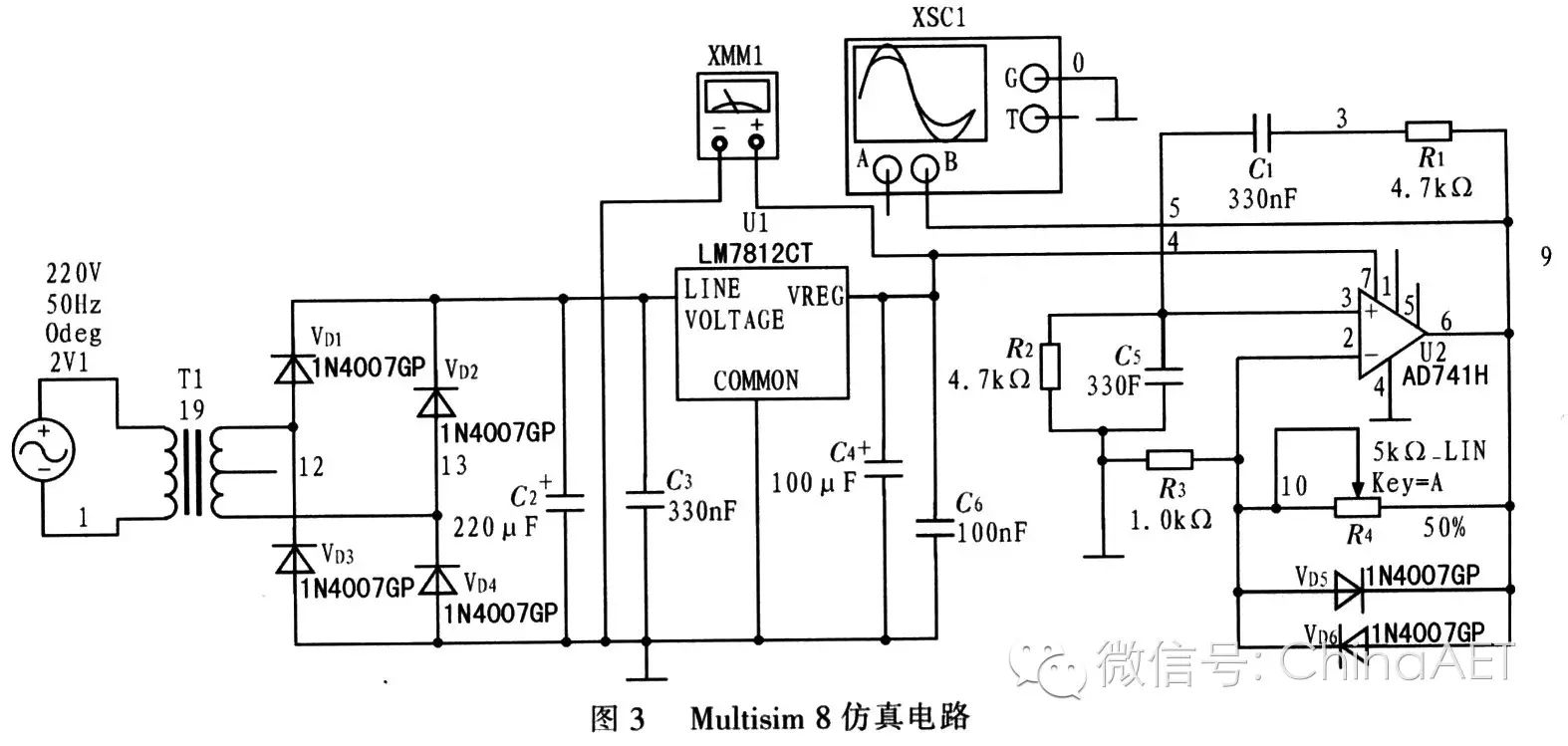
Using Multisim 8 to design a circuit that generates a 100 Hz, 0–500 mV (RMS) sine wave signal. Start Multisim 8 and establish the simulation circuit as shown in Figure 3 in its design window.
3.2 Circuit Simulation and Analysis in Multisim 8
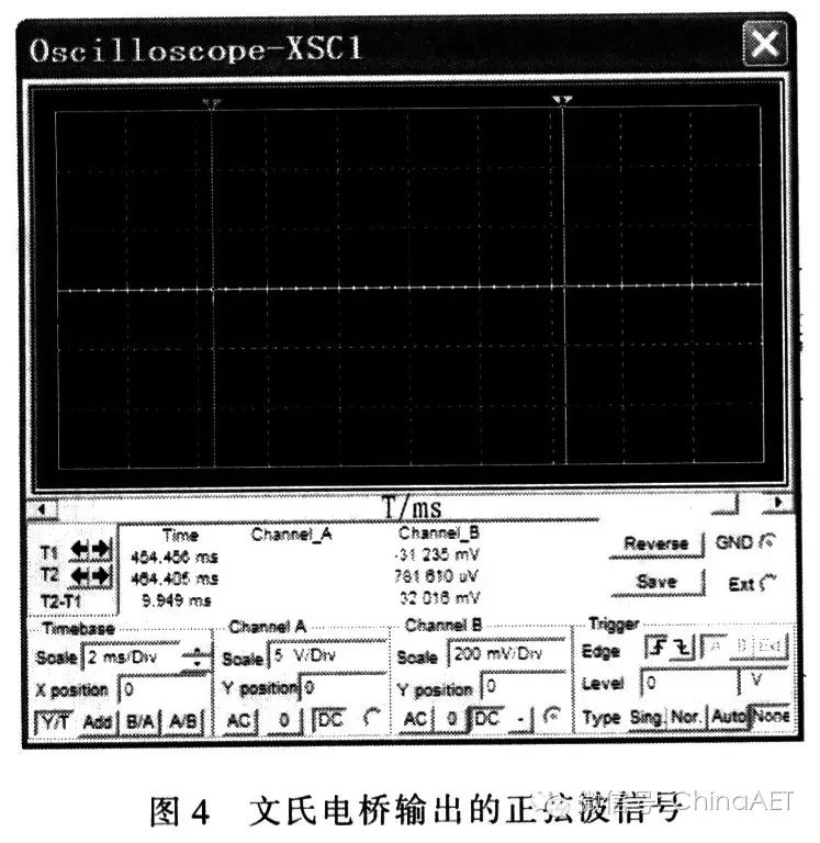
Run the simulation circuit and observe the output results using the virtual multimeter and oscilloscope. If the results do not meet the design requirements, the circuit needs to be modified and simulated again until the output is correct. Figure 4 shows the sine wave signal output from the Wien bridge; from Figure 4 (using cursor 1 and cursor 2 readings), the period of the sine wave is 9.949 ms, resulting in a frequency of 1000/9.949 = 100.5 Hz. The effective value of the signal measured by the probe is 269 mV, which meets the design requirements.
3.3 Output Netlist from Multisim 8
In Multisim 8, execute the menu Transfer/Transfer to other PCB Layout, and in the pop-up dialog box, select the file save type as Protel PCB (*.net), naming the file “Wien Bridge.net” and clicking the confirm button to complete the netlist output.
3.4 Input and Modify Netlist in Protel 99 SE
Start Protel 99 SE, create a new design library file, naming it “Wien Bridge.ddb”. Open its Documents folder and execute the File/Import command. In the dialog box, locate the netlist file “Wien Bridge.net” output from Multisim 8 and open it. Although this netlist is in Protel format, the component descriptions are still in Multisim 8 format, which needs to be converted to Protel format. The specific conversion process is shown in Table 1.
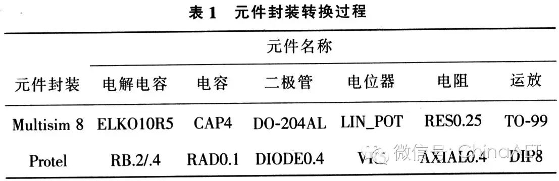
After modifying the netlist according to Table 1, save it. The package TO-220 of the three-terminal voltage regulator remains unchanged, as the transformer selected in the Multisim 8 simulation diagram is a virtual component, and its package needs to be custom-made in Protel.
3.5 Load Modified Netlist and Design PCB
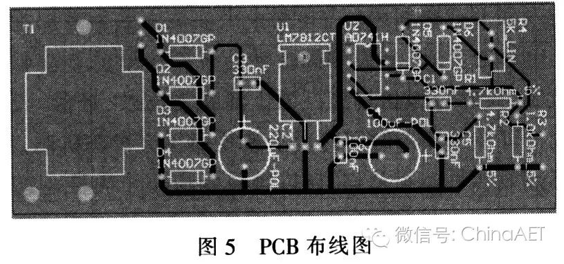
Create a new PCB document in the “Wien Bridge” design library, naming it “Wien Bridge.PCB”, and then start the PCB design process according to the previously mentioned PCB design flow. The layout is done manually, with the main wiring rules being: manual wiring, single-sided wiring, with a general line width of 20 mil for wiring and 40 mil for power and ground lines. Finally, add necessary mounting holes and input/output terminals. Figure 5 shows the final PCB wiring diagram, based on which the printed circuit board is made, followed by physical installation and debugging.
4 Conclusion
Both Multisim 8 and Protel 99 are commonly used EDA design tools. Multisim 8 has powerful circuit simulation and design capabilities, while Protel 99 is widely used for PCB design. This article introduces the basic process and methods from Multisim 8 circuit simulation to Protel 99 PCB design through a circuit example, providing a method for electronic circuit design that combines these two EDA software tools, achieving complementary advantages. This circuit design method is efficient, simple, practical, and has certain application prospects.