Microcontroller Serial Port
Communication Technology
The serial interface and communication of microcontrollers are core technologies for data transmission between devices in embedded systems.
1. Basics of Serial Communication
1.Serial vs Parallel Communication
Serial communication: Transmits data bit by bit, using fewer pins (14), suitable for long distances and low power consumption scenarios.
Parallel communication: Multiple data lines transmit simultaneously, faster but more costly, susceptible to interference, suitable for short distances (e.g., internal chip buses).
2.Core Concepts
Baud Rate (BaudRate): The number of symbols transmitted per second, must be consistent between both communicating parties (e.g., 9600, 115200).
Full Duplex/Half Duplex: Full duplex can send and receive simultaneously (e.g., UART), half duplex requires time division for sending and receiving (e.g., RS485).
Synchronization vs Asynchronous:
Synchronization: Relies on clock signals (e.g., SPI, I2C).
Asynchronous: No clock line, relies on start/stop bits (e.g., UART).
2. Common Serial Communication Protocols
1. UART (Universal Asynchronous Receiver-Transmitter)
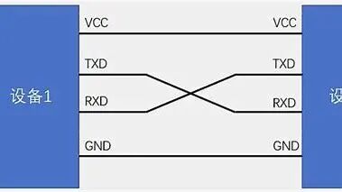
Features: Asynchronous, full duplex, requires TX (transmit), RX (receive) two lines.
Data frame format: Start bit (1)+Data bits (59)+Parity bit (optional)+Stop bit (12).
Applications: Microcontroller to PC (via USB to TTL), GPS modules, etc.
Disadvantages: No clock synchronization, relies on baud rate matching.
2. SPI (Serial Peripheral Interface)
Features: Synchronous, full duplex, four-wire system (SCK clock, MOSI master out slave in, MISO master in slave out, SS chip select).
Advantages: High speed (up to several MHz), high flexibility (data bits adjustable).
Applications: Flash memory, displays (e.g., OLED), high-speed ADC/DAC.
Disadvantages: More pin usage (each additional slave requires a chip select pin).
3. I2C (Inter-Integrated Circuit)
Features: Synchronous, half duplex, two-wire system (SDA data line, SCL clock line), supports multiple masters and slaves.
Addressing mechanism:7 bit or 10 bit device addresses, the master addresses the slave by address.
Advantages: Fewer pins, supports multiple devices (the limit on the bus is determined by capacitance).
Applications: Temperature and humidity sensors (e.g., SHT30), EEPROM storage.
Disadvantages: Lower speed (standard mode 100kbps, fast mode 400kbps).
4. Other Protocols1Wire: Single wire communication (e.g., DS18B20 temperature sensor).
CAN: High reliability, used in automotive and industrial networks.
USB: Complex protocol, requires dedicated controllers.
3. Key Points for Hardware Implementation
1.Level Standards
TTL:0V (logic 0), 3.3V/5V (logic 1), directly used for microcontroller pins.
RS232: ±12V level, requires conversion chip (e.g., MAX232) to connect to PC serial port.
RS485: Differential signal resistant to interference, supports multiple nodes (e.g., industrial field bus).
2.Interface Protection
Add TVS diodes, resistors to limit current, to prevent overvoltage/static damage.
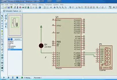
4. Software Implementation Example (using UART as an example)
Initialization code (C language)
//51 microcontroller UART initialization (baud rate 9600, crystal frequency 11.0592MHz)
void UART_Init(){
SCON=0x50;// mode 1 (8 bit UART), allow receiving
TMOD|=0x20;// timer 1 mode 2 (auto-reload)
TH1=0xFD;// baud rate 9600
TL1=0xFD;
TR1=1;// start timer 1
EA=1;// global interrupt enable
ES=1;//UART interrupt enable
}
// send a byte
void UART_SendByte(char dat){
SBUF=dat;
while(!TI);// wait for send completion
TI=0;// clear interrupt flag
}
// receive interrupt service function
void UART_ISR() interrupt 4{
if(RI){
char recv=SBUF;
RI=0;// clear receive flag
// process received data
}
}

5. Application Scenarios
1. UART: Connect to PC via CH340 chip, achieving debugging information output.
2. SPI: Drive TFT screens (e.g., ST7789 controller).
3. I2C: Read data from BMP280 barometric pressure sensor.
4. RS485: Connect multiple sensor nodes in industrial control.
6. Common Problems and Solutions
1. Data Corruption
Check if baud rate, data bits, and stop bits are consistent.
Confirm clock source accuracy (e.g., whether crystal error is too large).
2. Communication Failure
Measure signal line levels to see if they are normal.
Check wiring (e.g., TX/RX whether they are crossed).
Use a logic analyzer to capture waveforms and analyze timing.
3. Multi-Slave Conflict (I2C)
Ensure slave addresses are unique.
Add pull-up resistors (usually 4.7kΩ).
Protocol selection: Choose the appropriate protocol based on speed, distance, and number of devices.
Hardware design: Pay attention to level matching and anti-interference measures.
Software debugging: Use an oscilloscope or logic analyzer to verify communication timing.
END