In new energy vehicles, the MCU (Motor Control Unit) is sometimes referred to as an “inverter” or “electric control”. It is one of the “three core components” of electric vehicles (battery, motor, electric control), and its performance directly determines the vehicle’s driving experience, energy consumption, and reliability.The core function of the MCU is to accurately convert the high-voltage direct current (DC) output from the power battery into the three-phase alternating current (AC) required to drive the motor, and to adjust the motor’s speed and torque according to the instructions from the Vehicle Control Unit (VCU), thereby controlling the vehicle’s acceleration, deceleration, and constant speed operation. Its working principle can be broken down into four core steps: “signal reception – energy conversion – motor drive – state feedback”.Image source: Internet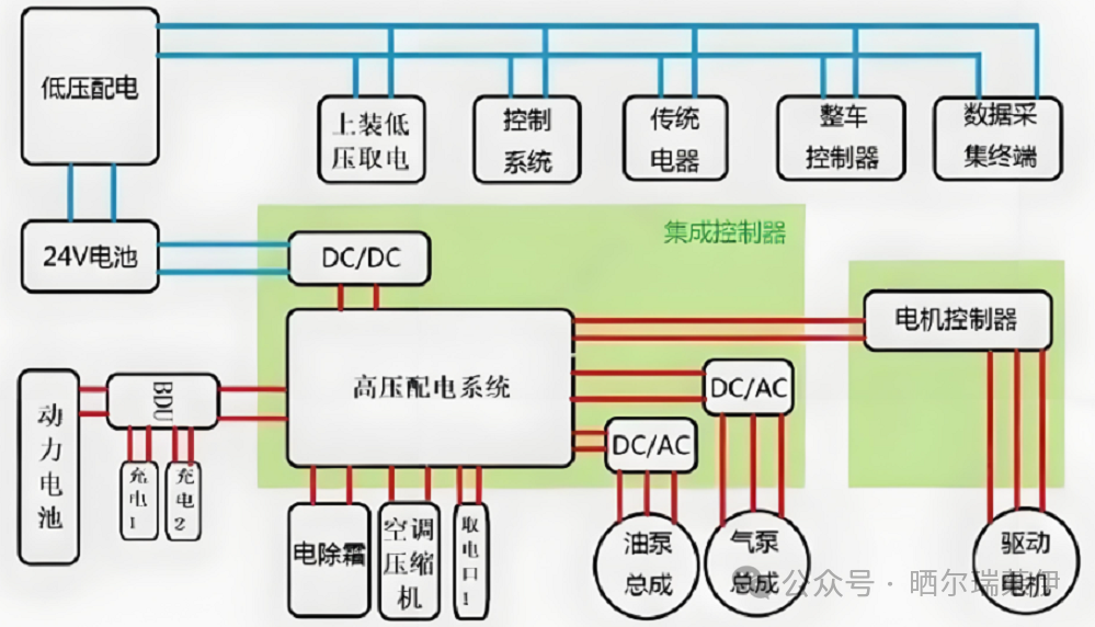 01 Signal Reception: Receiving Vehicle Control InstructionsWhen the vehicle is in motion, the driver’s actions are first transmitted to the Vehicle Control Unit (VCU). The VCU calculates the current required motor target torque/speed based on information such as accelerator pedal position, vehicle speed, battery SOC, and gear position, and then sends this instruction to the MCU via the CAN bus.02 Energy Conversion: Converting DC to ACThe power battery outputs high-voltage direct current (e.g., 300V~800V), while the drive motor of new energy vehicles (mainly permanent magnet synchronous motors) requires three-phase alternating current to operate. This conversion is accomplished by the MCU’s “inverter circuit”.The core of the inverter circuit consists of a “three-phase bridge inverter circuit” made up of 6 IGBTs (2 IGBTs per phase, divided into upper and lower bridge arms), with each IGBT acting as a “controllable switch”. The MCU’s main control chip outputs PWM (Pulse Width Modulation) signals to precisely control the “on/off” timing and duty cycle of the 6 IGBTs.By controlling the upper bridge arm IGBT of phase A to turn on and the lower bridge arm to turn off, while simultaneously controlling the lower bridge arm of phase B to turn on and the upper bridge arm to turn off, a current loop can be formed between phases A and B. By cyclically controlling the on sequence of the IGBTs in phases A, B, and C, three-phase alternating current with adjustable frequency and amplitude can be output (frequency determines motor speed, and amplitude determines motor torque).03 Motor Drive: AC Drives the Motor OperationThe three-phase alternating current converted by the inverter circuit is directly input into the stator windings of the drive motor.The current flowing through the stator windings generates a rotating magnetic field, and the rotor of the motor follows the rotation due to the “electromagnetic force” of the rotating magnetic field, converting electrical energy into mechanical energy. This mechanical energy is transmitted to the wheels through the reducer and drive shaft, ultimately driving the vehicle.04 State Feedback: Closed-loop Control and Safety ProtectionThe MCU does not simply output instructions once; instead, it employs a closed-loop control system through “sensor acquisition → feedback adjustment” to ensure that the motor operates according to the target while avoiding faults.Current sensors collect real-time current from the three phases of the motor, voltage sensors collect bus voltage, and temperature sensors collect the temperature of the IGBTs and the motor. The main control chip compares the “actual current/speed” with the “target current/speed”; if there is a deviation, it adjusts the PWM signal of the IGBTs in real-time to correct the output parameters of the alternating current, ensuring stable torque/speed. If abnormal signals are detected (e.g., excessive current, IGBT overheating, etc.), the MCU will immediately trigger protective mechanisms, such as reducing output power, cutting off IGBT output, or even reporting faults to the VCU to prevent damage to the motor or MCU, ensuring driving safety.Image source: Internet
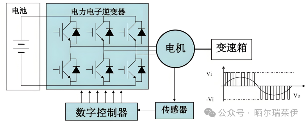 ——The MCU of new energy vehicles is a complex system that integrates power electronics technology, microelectronics technology, control theory, and thermal management technology. As an intelligent inverter, it precisely controls power semiconductors (IGBT/SiC) through a closed-loop algorithm based on vector control, converting the battery’s direct current into controllable alternating current to drive the motor and achieve efficient energy recovery.It is precisely the rapid development of MCU technology, such as the evolution from IGBT to more efficient SiC materials, that has enabled modern electric vehicles to achieve instantaneous acceleration performance, smooth driving experience, and longer range.