
Recently, Hongbin Yang, Liyu Zhu, Wei Li, Yinjiao Tang, Xiaomin Li, Ting Xu, Kun Liu, Chuanling Si, and others systematically summarized the construction strategies, macroscopic preparation processes, and microscopic structural design potentials of lignocellulose-mediated gel polymer electrolytes (L-GPEs). They analyzed the compatibility of their physicochemical structures with energy storage applications. Addressing the challenges faced by gel polymer electrolytes (GPEs) such as low ionic conductivity, poor interfacial compatibility, difficulties in large-scale production, and insufficient safety, they revealed the advantages of lignocellulose (cellulose, hemicellulose, lignin) in the preparation of GPEs. This study provides a first-time analysis of the key properties and construction strategies of L-GPEs from the perspective of lignocellulose, discussing future challenges and prospects in the energy storage field, thus providing direction for the design of advanced GPEs. 🎉🎉🎉 The related results “Lignocellulose-Mediated Gel Polymer Electrolytes Toward Next-Generation Energy Storage” were published in “Nano-Micro Letters”!! 🎉🎉🎉 Corresponding authors are Liyu Zhu, Ting Xu, Kun Liu, and Chuanling Si.
-
1
Introduction

The modern society’s surging demand for renewable energy has propelled the development of high-performance, environmentally friendly energy storage devices (such as supercapacitors, lithium-ion batteries, zinc-ion batteries, etc.). However, traditional liquid electrolytes pose safety issues such as leakage and flammability, and they can lead to dendrite growth that degrades performance. Solid polymer electrolytes (SPEs) can improve safety but suffer from poor interfacial compatibility and low ionic conductivity. Traditional gel polymer electrolytes (GPEs) combine the advantages of liquid and solid electrolytes but are limited by insufficient mechanical strength, limited thermal stability, and reliance on petrochemical materials, making it difficult to meet the sustainability and high-performance requirements of next-generation energy storage devices.
The authors systematically reviewed the challenges currently faced by GPEs, elucidating the opportunities and advantages of lignocellulose materials (cellulose, hemicellulose, lignin) in the preparation of energy storage device GPEs. They first analyzed and discussed the key properties (such as ionic conductivity, interfacial compatibility, etc.) and corresponding construction strategies of L-GPEs from the perspective of lignocellulose. They revealed differentiated regulation strategies for the matrix elements of lignocellulose (mechanical reinforcement from cellulose, interfacial stability from lignin, ion solvation from hemicellulose) to address common and specific bottlenecks of L-GPEs in different devices. They also emphasized methods to balance sustainability and high performance, and reviewed the applications of L-GPEs in various energy storage devices, concluding with a discussion on their future prospects and challenges.
-
2
Experiments

(1)Experimental reagents in different systems reviewed: lignocellulose (including cellulose, hemicellulose, lignin, sourced from wood, corn straw, sugarcane residue, straw, perennial grasses, etc.), polymers (such as polyvinyl alcohol (PVA), polyethylene glycol (PEG), poly(vinylidene fluoride-co-hexafluoropropylene) (PVDF-HFP), carboxymethyl cellulose (CMC), cellulose acetate (CA), polyacrylamide (PAM), etc.), electrolyte salts (such as lithium chloride (LiCl), zinc sulfate (ZnSO₄), zinc chloride (ZnCl₂), lithium hexafluorophosphate (LiPF₆), etc.), crosslinking agents (such as epichlorohydrin (ECH), polyethylene glycol diacrylate (PEGDA), etc.), inorganic fillers (such as silica (SiO₂), boron nitride (BN), lithium lanthanum titanate (LLTO) nanowires, etc.), solvents (such as dimethyl sulfoxide (DMSO), N,N-dimethylformamide (DMF), ethanol, etc.), and other additives (such as triphenylamine organic additives, hydrolyzed wool keratin, etc.).
(2)Experimental steps in different systems reviewed: during the preparation of lignocellulose materials, cellulose (such as cellulose nanocrystals (CNCs), cellulose nanofibers (CNFs), bacterial cellulose (BC)) is extracted from biomass through mechanical processing, enzymatic hydrolysis, or acid hydrolysis (such as sulfuric acid/formic acid mixed acid hydrolysis, FeCl₃-catalyzed maleic acid hydrolysis, etc.) and hemicellulose and lignin are separated; during the preparation of L-GPEs, solution casting methods (such as preparing lignocellulose films), electrospinning methods (such as coating nanohydrotalcite/PVDF-HFP composites on cellulose film surfaces), in-situ polymerization methods (such as in-situ polymerization of PETEA and CAP in liquid electrolytes), freeze-drying methods (such as directional freeze-drying to construct vertically aligned pore structures), crosslinking methods (chemical crosslinking such as ECH reacting with cellulose hydroxyls, physical crosslinking such as ethanol-induced hydrogen bond formation in cellulose), blending methods (such as blending lignocellulose with PVA, SA, potato starch, etc.) are employed; some also require chemical modification of lignocellulose (such as sulfonation, acetylation, chlorination, grafting with acrylic acid, etc.) to optimize performance.
(3)Testing and characterization methods in different systems reviewed: scanning electron microscopy (SEM) and transmission electron microscopy (TEM) are used to observe the micro-morphology and structure of materials; X-ray diffraction (XRD) is used to analyze the crystallinity of cellulose; thermogravimetric analysis (TGA) and differential scanning calorimetry (DSC) are used to assess thermal stability; electrochemical impedance spectroscopy (EIS) is used to test ionic conductivity and interfacial resistance; cyclic voltammetry (CV) and galvanostatic charge-discharge tests (GCD) are used to analyze electrochemical performance (such as cycling stability, rate performance, Coulombic efficiency); tensile tests are used to test mechanical properties (tensile strength, elongation at break); contact angle measurements are used to assess interfacial wettability; and X-ray photoelectron spectroscopy (XPS) is used to analyze the interfacial chemical composition, with some combining in-situ characterization techniques (such as in-situ EIS) to monitor changes in material performance during charge and discharge.
Q: What is the role of each component? (1) Cellulose: serves as the framework material for the gel electrolyte, providing stable mechanical support. Its three-dimensional crosslinked porous structure and high crystallinity significantly enhance the mechanical strength of L-GPEs (e.g., L-GPEs have a compressive strength exceeding 40MPa, more than 8 times that of PEO-GPE), physically blocking dendrite growth paths; the abundant hydroxyl groups on the surface promote electrolyte wetting, and the nanoscale pores (such as those in CNFs) provide low-curvature ion transport channels, enhancing ionic conductivity. (2) Hemicellulose: acts as a branched copolymer, wrapping around cellulose to provide filling and compressive support; its rich branched structure and hydrophilic groups (carboxyl, hydroxyl) give it high liquid absorption capacity, allowing it to absorb a large amount of liquid electrolyte to increase ion concentration in the electrolyte, providing more ionic conduction carriers, while the filled liquid electrolyte forms continuous ion transport channels, enhancing ion mobility and conductivity. Its flexible segments can alleviate the spatial hindrance of Na⁺ solvation shells, promoting ion conduction. (3) Lignin: as a three-dimensional amorphous heteropolymer, crosslinking the fiber structure endows L-GPEs with excellent thermal stability (initial decomposition temperature exceeding 320℃, 120℃ higher than traditional PEO-based GPEs, with some lignin decomposition temperatures exceeding 400℃); it has free radical scavenging ability, which can delay electrolyte combustion; the hydrophobic three-dimensional crosslinked network enhances thermal stability and suppresses solvent leakage; the aromatic rigid skeleton and phenolic hydroxyl groups provide electrochemical protection, and the hydrophobic benzene rings can orient at the electrode interface to form mechanical barriers that inhibit dendrite growth, while also chelating Zn²⁺ to alter the solvation structure of the zinc anode, suppressing zinc dendrites. (4) Polymers (such as PVA, PEG, PVDF-HFP, etc.): blended or crosslinked with lignocellulose to improve the mechanical properties (e.g., PVA and BC form a double network structure that enhances tensile strength), flexibility, and film-forming ability of L-GPEs; some polymers (such as PVDF-HFP) with high dielectric constants can promote ion dissociation, improve interfacial compatibility, and reduce side reactions with electrodes. (5) Inorganic fillers (such as SiO₂, BN, LLTO nanowires, etc.): uniformly dispersed in GPEs, can enhance thermal stability (e.g., SiO₂ extends the decomposition temperature range, BN suppresses the low-temperature evaporation of organic solvents); some fillers (such as LLTO nanowires) can assist in ion transport, and LLTO can also avoid direct contact with lithium metal to reduce side reactions; nanohydrotalcite can act as a Li⁺ transport redistributor, promoting uniform deposition of Li⁺ and reducing lithium dendrites. (6) Electrolyte salts (such as LiCl, ZnSO₄, LiPF₆, etc.): provide mobile ions (such as Li⁺, Zn²⁺, Na⁺), which are the core carriers of ionic conduction; some salts (such as ZnCl₂) can also act as pore formers and salt additives, optimizing the gel network structure and ionic conductivity.
-
3
Illustrative Analysis

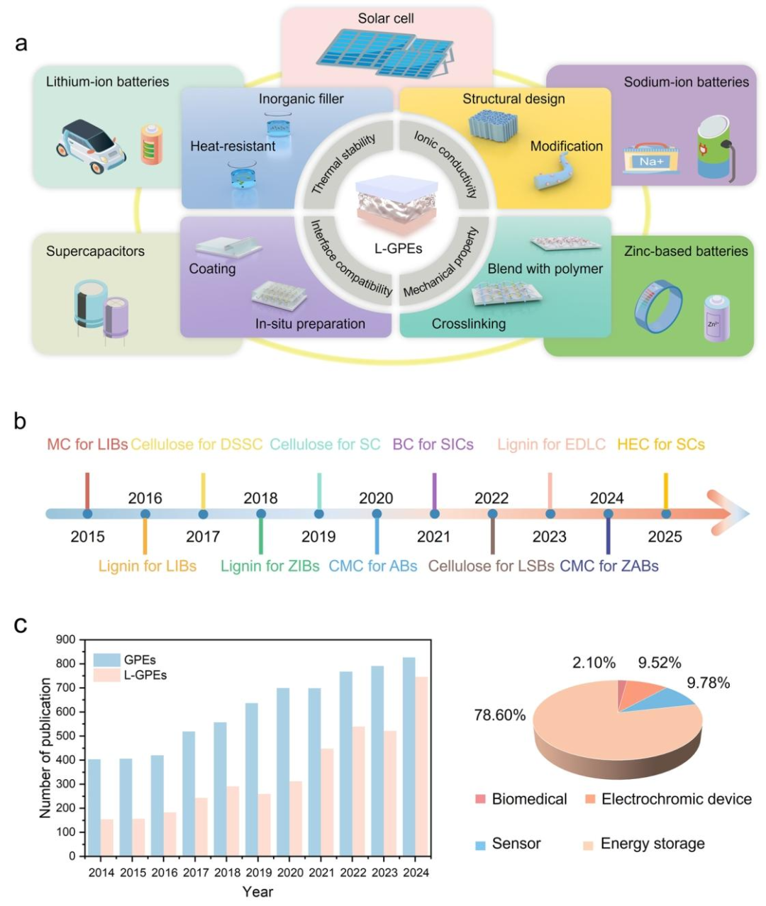 ▲ Figure 1: a shows the key requirements, preparation methods, and applications of L-GPEs in energy storage devices; b shows the timeline of representative L-GPEs development; c shows the annual changes in the number of publications related to L-GPEs since 2014 and the distribution of different GPEs publications from 2015 to 2025.
Figure 1: The main content presents the overall situation of L-GPEs in the energy storage field. In terms of data, the timeline (b) shows the development milestones of representative L-GPEs from 2016 to 2024, such as the use of MC in lithium-ion batteries in 2016 and cellulose in DSSCs in 2018; the publication statistics (c) show that the number of papers related to L-GPEs has increased year by year since 2014, with a significant increase around 2025, and the proportion of publications in the energy storage field reaching 78.60%, with the proportion of L-GPEs gradually increasing in GPEs-related publications (e.g., 2.10%, 9.52%, 9.78%).
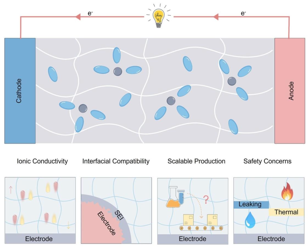 ▲ Figure 2: Illustrates the main challenges faced by GPEs in energy storage, including ionic conductivity, interfacial compatibility, large-scale production, and safety (leakage, SEI film, thermal issues) in relation to electrodes.
Figure 2: The main content summarizes the four core challenges of GPEs in energy storage applications. No specific numerical data is provided, and the schematic form presents how insufficient ionic conductivity affects ion transport efficiency, poor interfacial compatibility leads to high interfacial impedance and severe polarization, difficulties in large-scale production limit practical applications, and safety issues (such as electrolyte leakage and thermal runaway) threaten device stability, visually demonstrating the relationship between each challenge and the electrodes and electrolytes.
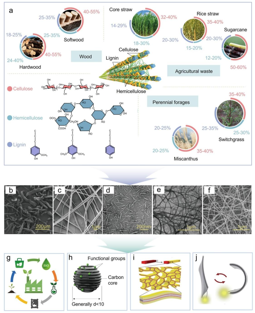 ▲ Figure 3: a shows the sources and composition of lignocellulose materials; b-f show the morphology of carboxymethyl cellulose (CMC), cellulose acetate (CA), cellulose nanocrystals (CNCs), cellulose nanofibers (CNFs), and bacterial cellulose (BC); g-j illustrate the renewability, high carbon content, porous structure, and mechanical properties of lignocellulose materials.
Figure 3: The main content systematically introduces the sources, composition, morphology, and properties of lignocellulose. In terms of data, the sources and composition (a) show the component ratios of different lignocellulose raw materials, such as hardwood containing 40%-55% cellulose, 24%-40% hemicellulose, and 18%-25% lignin, softwood containing 40%-45% cellulose, 25%-35% hemicellulose, and 25%-35% lignin, and corn straw containing 32%-40% cellulose; the morphology images (b-f) display the microstructures of different cellulose derivatives, such as CNCs being rigid rod-like (diameter 5-50nm, length 100-500nm), and CNFs having a diameter of less than 100nm; the performance section (g-j) emphasizes their renewability, high carbon content (high carbon content after high-temperature carbonization), porous structure (such as high porosity), and excellent mechanical properties (such as cellulose Young’s modulus of about 138GPa).
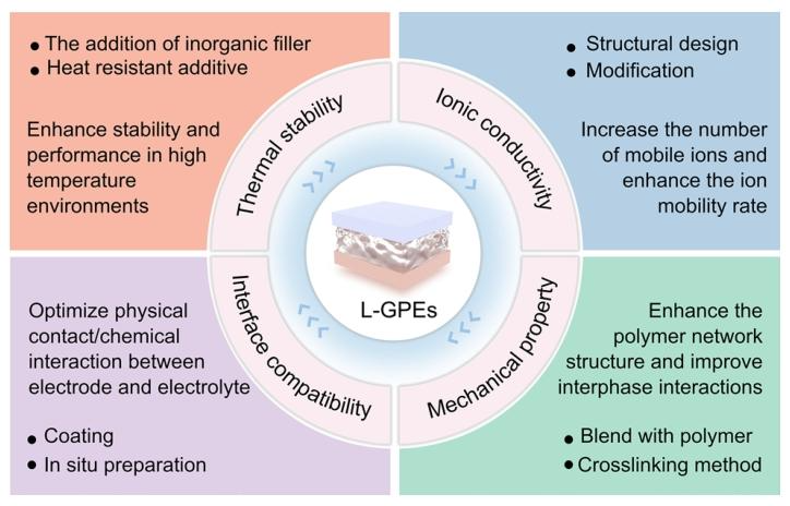 ▲ Figure 4: Illustrates the key requirements and engineering strategies for L-GPEs in energy storage, including enhancing thermal stability (adding heat-resistant additives, inorganic fillers), ionic conductivity (structural design, modification), interfacial compatibility (coating, in-situ preparation), and mechanical properties (blending with polymers, crosslinking).
Figure 4: The main content organizes the key performance requirements of L-GPEs in energy storage and corresponding engineering optimization strategies. No specific numerical data is provided, and the schematic form categorizes the methods to enhance thermal stability (adding heat-resistant additives such as PI, inorganic fillers such as BN), ionic conductivity (structural design such as vertical channels, chemical modification such as sulfonation), interfacial compatibility (coating such as PVDF-HFP coating, in-situ preparation such as in-situ polymerization), and mechanical properties (blending with polymers such as HEC/LC blending, crosslinking such as chemical/physical crosslinking), clarifying the relationship between each strategy and performance enhancement.
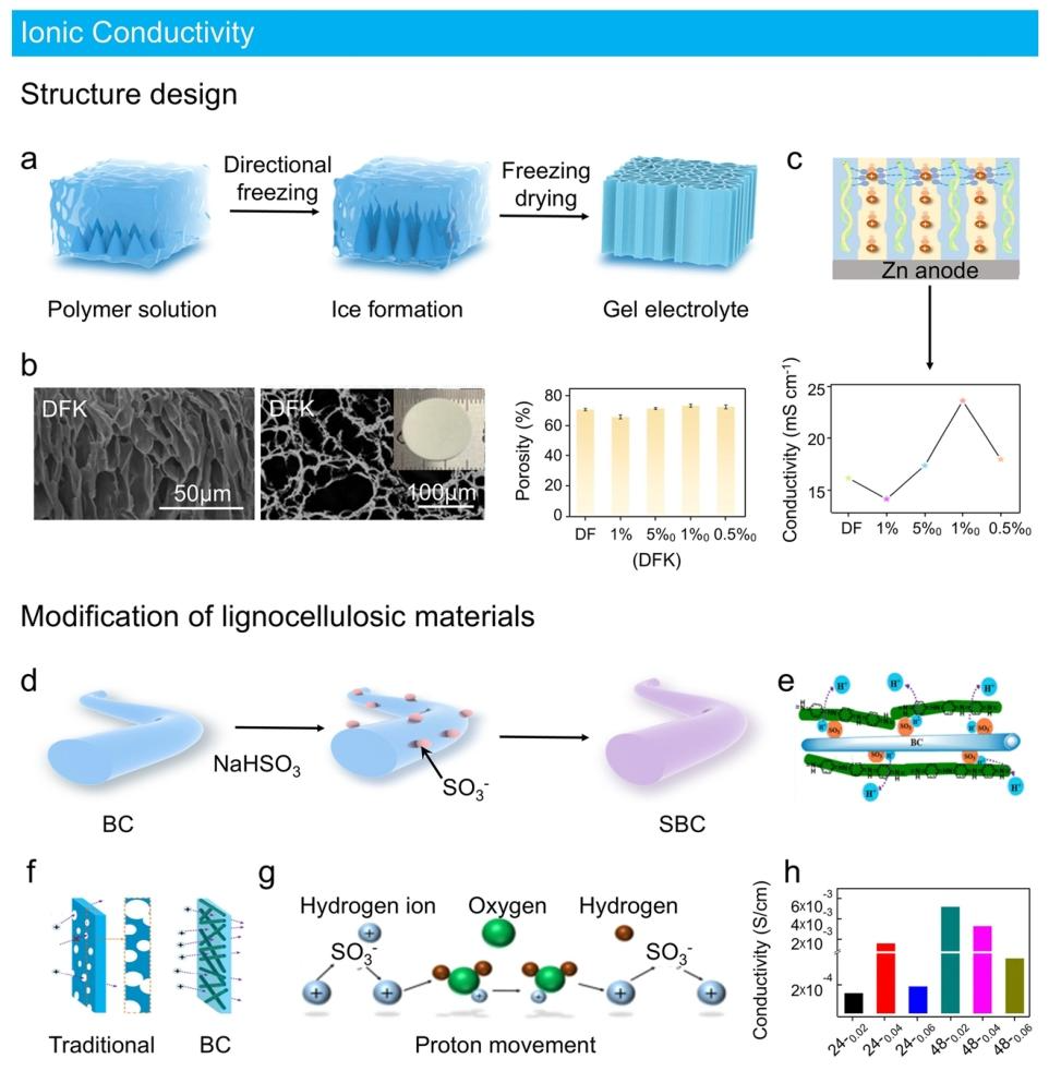 ▲ Figure 5: a illustrates the schematic of preparing gel electrolytes through structural design (directional freezing – freeze-drying); b shows the SEM image of DFK and its porosity data; c illustrates the ion transport mechanism in DFK electrolytes and its ionic conductivity data; d illustrates the schematic of preparing gel electrolytes through lignocellulose modification; e shows the proton transport schematic in SBC/PANI GPEs; f compares the ion transport of traditional porous electrolytes with SBC/PANI GPEs; g illustrates the formation of a “water bridge”; h shows the ionic conductivity data of SBC/PANI membranes.
Figure 5: The main content elaborates on two core strategies (structural design, lignocellulose modification) to enhance the ionic conductivity of L-GPEs and their effects. In terms of data, in the structural design (a-c), the DFK gel electrolyte prepared by directional freeze-drying has a porosity of 73.4%, electrolyte absorption rate of 1777%, ionic conductivity of 23.6mS/cm, mechanical strength of 2.0MPa, and the assembled K/Zn biomimetic battery has a discharge specific capacity of 68.0mAh/g at 1mA/cm², with a capacity retention rate of 85.3% after 1000 cycles and an energy density of 134.5Wh/kg, power density of 5.2kW/kg; the ionic conductivity of cellulose zinc gel treated with ethanol vapor for 6 hours reaches 8.39mS/cm; in the modification strategy (d-h), the room temperature ionic conductivity of cellulose polyionic liquid (PILs)/PVA gel electrolyte is 4.2mS/cm, the Li⁺ transference number of modified cellulose GPE is 0.902, ionic conductivity is 4.36×10⁻³S/cm, and the ionic conductivity of SBC/PANI membrane with a sulfonation degree of 41.87% is 5.2×10⁻³S/cm with an ion exchange capacity of 3.92mequiv.
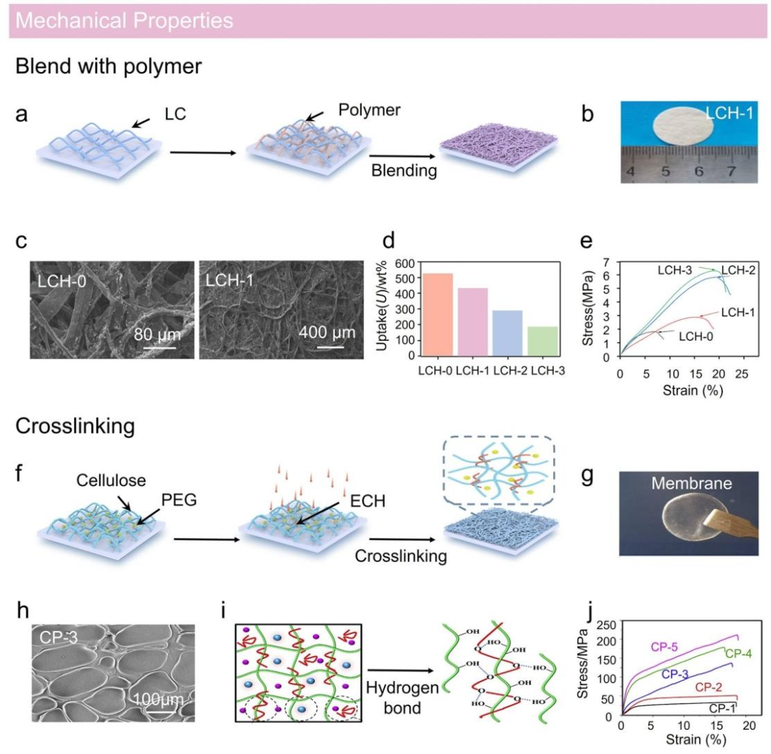 ▲ Figure 6: a illustrates the schematic of preparing gel electrolytes through blending with polymers; b shows the structural schematic of LCH series GPEs; c shows the SEM images of LCH-0 and LCH-1; d shows the liquid electrolyte absorption rate data of LCH membranes; e shows the stress-strain curves of GPEs; f illustrates the schematic of preparing gel electrolytes through crosslinking; g shows the structural schematic of composite membranes; h shows the SEM images of composite membranes; i illustrates the ion transport mechanism in GPEs; j shows the stress-strain curves of composite membranes.
Figure 6: The main content introduces two key methods (blending with polymers, crosslinking) to enhance the mechanical properties of L-GPEs and their effects. In terms of data, in the blending strategy (a-e), the tensile strength of the LCH-2 membrane blended with HEC/LC is 5.85MPa, the mechanical strength of the SA/LC blended membrane (SA20wt%) is more than 4 times that of the pure LC membrane, and the tensile strength of the potato starch/LC blended membrane (starch 5wt%) is more than 6 times that of the pure LC membrane, and the liquid electrolyte absorption rate of the HEC/LC blended membrane changes with the increase of HEC content; in the crosslinking strategy (f-j), the tensile strength of the cellulose/PVA composite hydrogel (5% cellulose) is 306kPa (higher than the 182kPa of pure PVA), with a breaking elongation of 1106%, the mechanical strength of BC/PVA hydrogel (6-BPCE) is 0.951MPa (9 times that of pure PVA), and the mechanical strength of the double-crosslinked cellulose hydrogel electrolyte (DCZ-gel) is 2.08MPa, with a breaking elongation of 145%, ionic conductivity of 38.6mS/cm, and the breaking strength of the hydrolyzed wool keratin/CMC composite gel electrolyte is 58MPa with a breaking elongation of 6.3%, while the tensile strength of the cellulose/PEG crosslinked GPE increases from 33.92MPa to 211.06MPa.
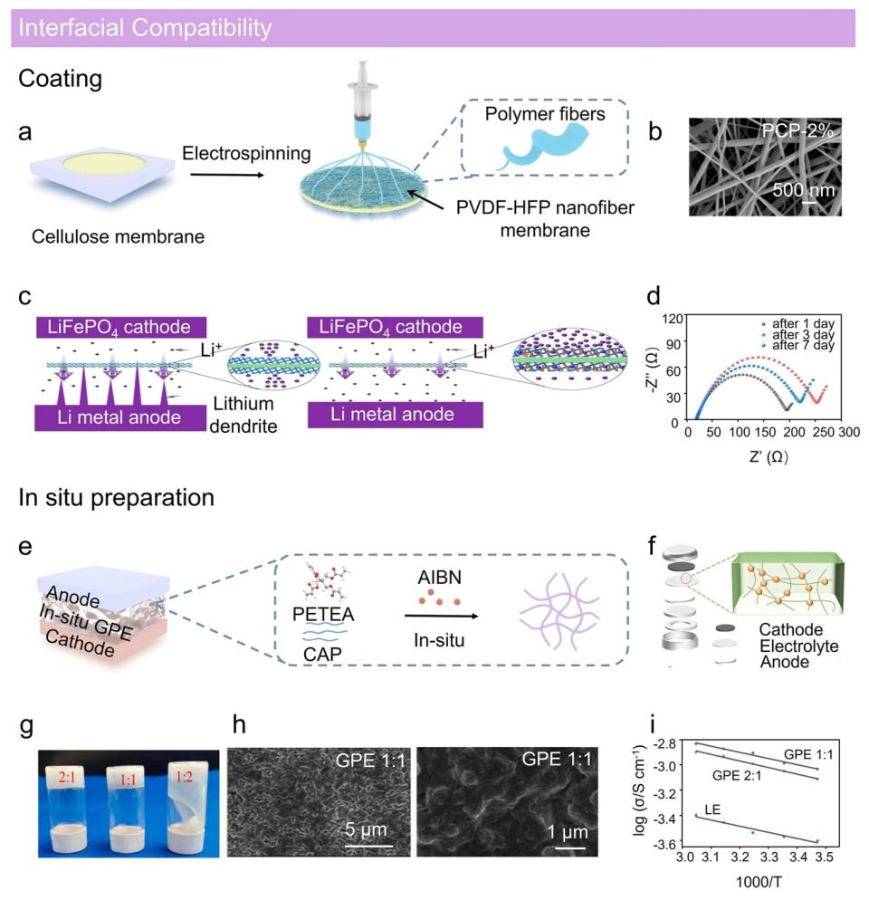 ▲ Figure 7: a illustrates the schematic of preparing gel electrolytes through coating technology (electrospinning); b shows the SEM images of PCPs; c illustrates the mechanism of nanohydrotalcite as a lithium ion transport redistributor; d shows the EIS images of lithium symmetric batteries; e illustrates the schematic of preparing gel electrolytes through in-situ preparation; f shows the structural schematic of GPEs; g shows optical photos of GPEs with different PETEA/CAP ratios; h shows the SEM images of GPEs; i shows the Arrhenius plots of GPE 1:1, GPE 2:1, and liquid electrolytes (LE).
Figure 7: The main content explains two important techniques (coating, in-situ preparation) to improve the interfacial compatibility of L-GPEs and their effects. In terms of data, in the coating strategy (a-d), the nanohydrotalcite/PVDF-HFP coated cellulose GPE (PCPs) prepared by electrospinning has the lowest interfacial impedance of 194.5Ω (far lower than that of CM), which can promote uniform deposition of Li⁺; the dual-functional asymmetric cellulose gel electrolyte (QACA combined with Di-UiO66/BP coating) has a contact angle of 9.6°, showing good adsorption and catalytic effects on LiPSs, with excellent interfacial compatibility; in the in-situ preparation strategy (e-i), the activation energy of the PETEA/CAP in-situ polymerized GPE is 0.040eV (lower than that of liquid electrolytes), with a fast Li⁺ migration rate, forming a stable SEI film (rich in LiF), inhibiting Li dendrites and solvent decomposition, with a capacity retention rate of 90.6% after 500 cycles.
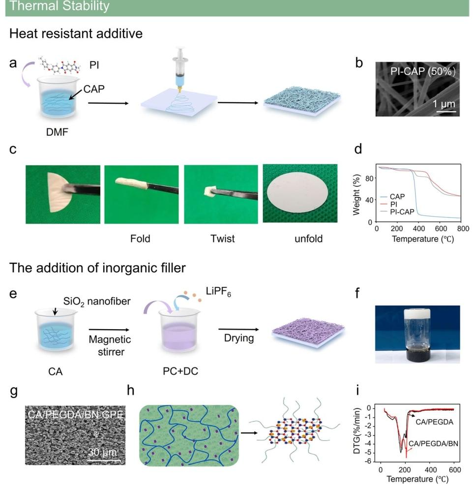 ▲ Figure 8: a illustrates the schematic of preparing gel electrolytes by adding heat-resistant additives; b shows the SEM images of PI-CAP; c shows photos of PI-CAP membranes folded, twisted, and unfolded; d shows the TG curves of PI, CAP, and PI-CAP membranes; e illustrates the schematic of preparing gel electrolytes by adding inorganic fillers; f shows photos of PEGDA; g shows the SEM images of PEGDA; h illustrates the Lewis acid-base interaction of BN with polymers or anions; i shows the DTG curves of GPEs.
Figure 8: The main content presents two effective approaches (adding heat-resistant additives, inorganic fillers) to enhance the thermal stability of L-GPEs and their effects. In terms of data, in the heat-resistant additive strategy (a-d), the tensile strength of the PI-CAP composite membrane is 7.1MPa, with thermal stability exceeding 200℃, and it has super flexibility (can be folded and twisted); the residual mass of the PVDF-HFP/CA composite membrane (PFP-CA) is 17.71% at high temperatures (higher than the 12.17% of pure PFP membrane); in the inorganic filler strategy (e-i), the first stage decomposition temperature range of g-SiO₂/CA gel electrolyte is widened from 264-290.53℃ to 255-346℃, with the second stage decomposition temperature reaching 622℃; the CA/PEGDA/BN GPE has a maximum decomposition rate of 5.6%/min for organic solvents at 210℃ (higher than the 3.3%/min of CA/PEGDA GPE), with a weight loss rate of 67.8% (lower than the 72.9% of CA/PEGDA GPE), indicating better thermal stability.
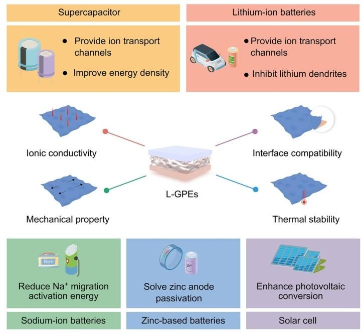 ▲ Figure 9: Illustrates the key requirements and applications of L-GPEs in energy storage devices, showing their roles in supercapacitors, lithium-ion batteries, sodium-ion batteries, zinc-based batteries, and solar cells (such as providing ion transport channels, inhibiting dendrites, enhancing energy density, etc.).
Figure 9: The main content summarizes the key requirements and core roles of L-GPEs in different energy storage devices. No specific numerical data is provided, and the schematic clearly shows their roles in providing ion transport channels and enhancing energy density in supercapacitors, inhibiting lithium dendrites in lithium-ion batteries, reducing Na⁺ migration activation energy in sodium-ion batteries, solving zinc anode passivation issues in zinc-based batteries, and enhancing photoelectric conversion efficiency in solar cells, all of which need to meet four key requirements: ionic conductivity, mechanical properties, interfacial compatibility, and thermal stability.
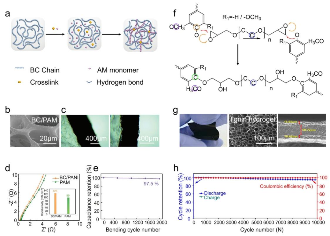
 ▲ Figure 10: a illustrates the schematic of preparing BC/PAM hydrogel; b shows the SEM images of BC/PAM hydrogel; c shows the cross-sectional image of the electrode-electrolyte interface and a photo of a four-cell ASC driving a small fan; d shows the EIS of BC/PAM and PAM hydrogels; e shows the CV curves of all-solid-state symmetric devices; f illustrates the crosslinking reaction of lignin with PEGDGE; g shows the digital photos and SEM images of PEGDGE; h shows the long-term cycling stability and Coulombic efficiency of lignin-based supercapacitors at 5A/g.
Figure 10: The main content showcases the applications and performance of L-GPEs in supercapacitors. In terms of data, the CNC-enhanced hydrogel electrolyte (CNC-G-12) has a stress of 210.98kPa, strain of 2204%, and ionic conductivity of 0.207±0.005S/cm, with the assembled supercapacitor having a capacitance of 67.31F/g at 0.05A/g and a capacity retention rate of nearly 100% after 2200 cycles at 0.1A/g; the BC/PAM hydrogel has a tensile strength of 330kPa (higher than the 70kPa of pure PAM), ionic conductivity of 125mS/cm, and the assembled supercapacitor maintains a capacity retention rate of 97.5% after 2000 bends; the PAM/LiCl/WSCA hydrogel remains flexible at -80℃, with an ionic conductivity of 23.1S/cm, and the assembled supercapacitor remains stable after 500 folds and 10000 charge-discharge cycles, maintaining a capacity of 64.64% at -40℃; the all-lignin-based supercapacitor has a Coulombic efficiency exceeding 99% after 10000 cycles at 5A/g, maintaining stability at different bending angles.
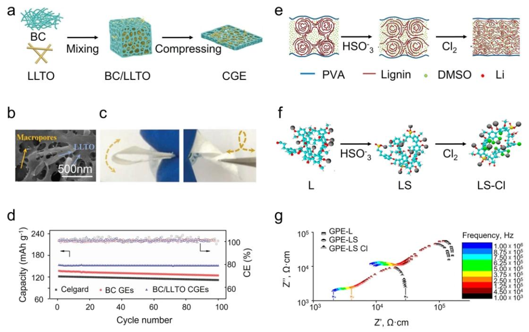 ▲ Figure 11: a illustrates the schematic of preparing BC/LLTO CGEs; b shows the SEM images of BC/LLTO CGEs; c shows the high flexibility of the BC/LLTO CGE matrix; d shows the cycling performance of BC/LLTO CGE; e illustrates the schematic of preparing GPE-LS; f shows the fragment structures of L, LS, and LS-Cl molecules; g shows the impedance spectra related to L, LS, and LS-Cl molecules.
Figure 11: The main content presents the applications and performance of L-GPEs in lithium-ion batteries. In terms of data, the Young’s modulus of BC/LLTO CGEs is 1.15GPa, with a Li⁺ transference number of 0.88, and the assembled half-cell shows no significant capacity decay after 100 cycles at 0.2C, effectively suppressing Li dendrites; the crosslinked cellulose gel membrane (5% crosslinking agent) has high ionic conductivity, with the assembled battery showing an initial discharge capacity of 145mAh/g and a capacity retention rate of 90% after 50 cycles; the GPE assembled from acetylated CNFs shows an initial discharge capacity of 153mAh/g at 0.2C, with a capacity retention rate of 88.8%; the ionic conductivity of the sulfonated chlorinated lignin/PVA gel electrolyte (GPE-LS-Cl) is 2.48×10⁻⁴S/cm, which can enhance the charge-discharge rate and cycling stability of the battery.
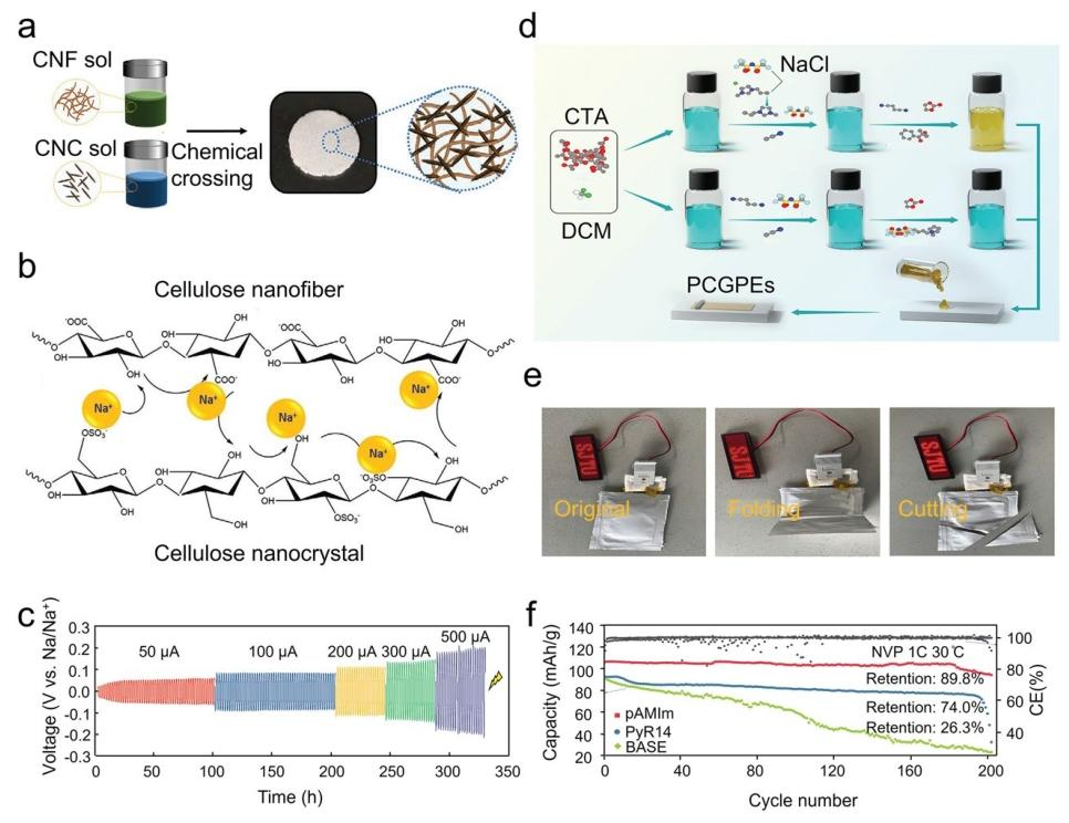 ▲ Figure 12: a illustrates the schematic of preparing CNC/CNF frozen gel; b illustrates the ion conduction mechanism in Na⁺ in the nanofiber GPE; c shows the voltage-time curve of Na/Na symmetric batteries at room temperature; d illustrates the preparation route of PCGPEs; e shows a photo of the NVP-Na soft-pack battery lighting a lamp; f shows the cycling performance of the NVP/Na battery.
Figure 12: The main content showcases the applications and performance of L-GPEs in sodium-ion batteries. In terms of data, the ionic conductivity of the CNC/CNF frozen gel GPE is 2.32mS/cm, with a Na⁺ transference number of 0.637, and the assembled sodium-ion battery shows a specific capacity of 69.7mAh/g after 50 cycles at 1C, with an energy density of 240Wh/kg; the CTA-based PCGPEs assembled soft-pack battery can discharge even after folding and cutting, maintaining a capacity retention rate of 89.8% after 200 cycles, with a capacity of 106.0mAh/g at 0.1C and 95.1mAh/g at 2C (with a capacity retention rate of 89.7%); the BC-GPE has a tensile strength of 36MPa, maximum strain of 31.23%, and the assembled sodium-ion battery shows a capacity decay rate of only 0.005% after 1250 cycles.
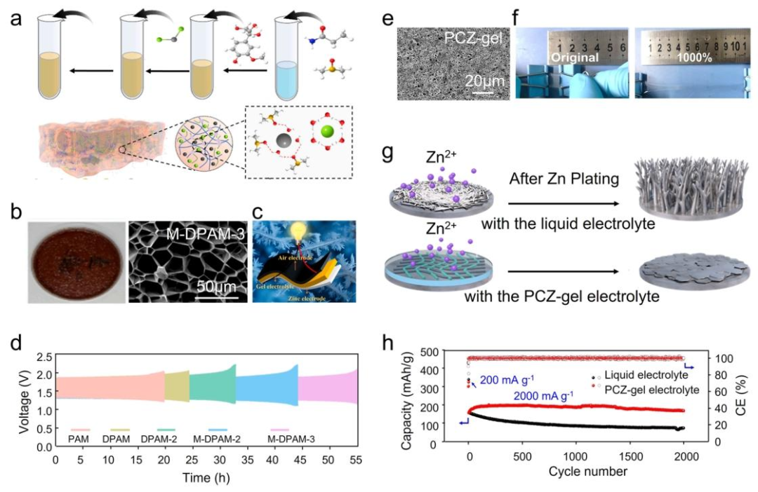
 ▲ Figure 13: a illustrates the schematic of preparing M-DPAM-3 hydrogel electrolyte; b shows the photos and SEM images of M-DPAM-3 hydrogel electrolyte; c illustrates the structure of flexible zinc-air batteries; d shows the cycling performance of flexible batteries; e shows the SEM images of PCZ gel; f shows the photos of PCZ gel under stretching; g illustrates the zinc deposition behavior; h shows the long-term cycling performance at 2000mA/g.
Figure 13: The main content presents the applications and performance of L-GPEs in zinc-based batteries. In terms of data, the ionic conductivity of M-DPAM-3 hydrogel electrolyte is 440.91mS/cm, with a cycling life extended by 175% compared to traditional PAM hydrogels (reaching 55h); the “Cellyte” amorphous cellulose electrolyte assembled Zn//cell-4.5//LMO-CF full battery has a cycling life exceeding 1000h, with a capacity retention rate of 90.6%; the carboxyl-functionalized cellulose hydrogel electrolyte assembled zinc-ion batteries shows a specific capacity of 244mAh/g after 1500 cycles (with a retention rate of 80% compared to the maximum of 306mAh/g); the PMC hydrogel electrolyte assembled battery shows an initial specific capacity of 380.74mAh/g at 1.0A/g, with a capacity retention rate of 71.1%; the PCZ gel can stretch 10 times, and the assembled Zn//NVO battery shows a reversible specific capacity of 226mAh/g, with a capacity retention rate of 84% after 150 cycles, effectively suppressing Zn dendrites.
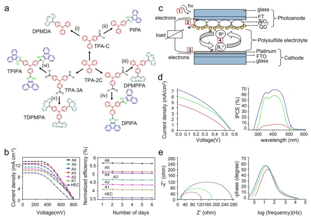
 ▲ Figure 14: a illustrates the structure of dye-sensitized solar cells; b shows the I-V curve and stability curve of the gel electrolyte; c illustrates the working schematic of quantum dot-sensitized solar cells (QDSSC); d shows the IPCE curve and J-V characteristic curve of QDSSC; e shows the Nyquist plot and Bode phase plot of QDSSC.
Figure 14: The main content showcases the applications and performance of L-GPEs in solar cells. In terms of data, the hydroxyethyl cellulose/triphenylamine additive gel electrolyte used in DSSCs shows no significant changes in performance within 6 days, with stable I-V curves; the methyl cellulose-polysulfide gel electrolyte used in QDSSCs shows an IPCE value of 57.24% for the structure of TiO₂/CdS₅/ZnS₂/electrolyte/Pt, which increases to 67.20% after adding a SiO₂ passivation layer (TiO₂/CdS₅/ZnS₂/SiO₂(2h)/electrolyte/Pt), and the Nyquist and Bode phase plots show excellent device impedance characteristics and stable photoelectric conversion performance.
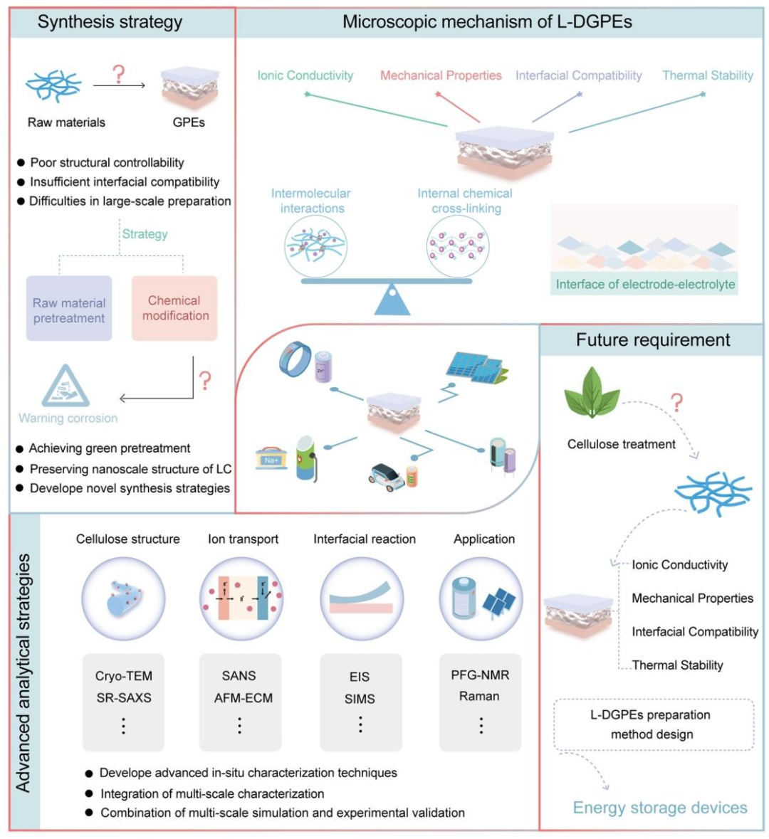
 ▲ Figure 15: Illustrates the preparation strategies, microscopic mechanisms, advanced characterization, and future development of L-GPEs for energy storage devices, including synthesis strategies (raw material pretreatment modification, interfacial design), microscopic mechanisms (ion transport, interfacial reactions), advanced characterization techniques (cryogenic transmission electron microscopy, small-angle neutron scattering, etc.), and future needs.
Figure 15: The main content looks forward to the future development directions of L-GPEs for energy storage devices, covering preparation strategies, microscopic mechanisms, and advanced characterization techniques. No specific numerical data is provided, and it clarifies that preparation strategies need to address issues such as green pretreatment of raw materials, controllability of structures, and large-scale production; microscopic mechanisms need to study the balance of chemical crosslinking and intermolecular interactions, optimizing dynamic interfacial design; advanced characterization needs to develop in-situ techniques (such as in-situ EIS, CV), integrate multi-scale characterization (such as combining SEM with macro performance testing), and combine multi-scale simulations with AI technology to promote L-GPEs from laboratory to practical applications.
-
4
Scientific Inspiration

Q: Why do the materials prepared in this paper exhibit excellent performance?🟢️The excellent performance of the prepared lignocellulose-mediated gel polymer electrolytes (L-GPEs) is primarily due to the synergistic effect of the inherent properties of lignocellulose and reasonable engineering design strategies. From the perspective of lignocellulose components, the three-dimensional crosslinked porous structure and high crystallinity of cellulose provide outstanding mechanical support, physically blocking dendrite growth, while its abundant hydroxyl groups promote electrolyte wetting, and the nanoscale pores construct low-curvature ion transport channels; the highly branched structure and hydrophilic groups (carboxyl, hydroxyl) of hemicellulose endow it with high liquid absorption capacity, increasing the ion concentration in the electrolyte and forming continuous ion transport channels, enhancing ion migration efficiency; the three-dimensional crosslinked network and aromatic rigid skeleton of lignin not only provide excellent thermal stability (initial decomposition temperature exceeding 320℃) and flame retardancy but also inhibit dendrite growth and stabilize the electrode-electrolyte interface through interfacial interactions. In engineering design, structural design (such as directional freezing to construct vertical channels, solution casting to prepare high-porosity membranes) further optimizes ion transport paths, reducing transport resistance; chemical modifications (such as sulfonation, acetylation) can enhance the interaction between lignocellulose and the electrolyte, improving ion dissociation and migration capabilities; blending (such as with PVA, SA) or crosslinking (such as forming covalent networks through chemical crosslinking, hydrogen bond networks through physical crosslinking) can significantly enhance mechanical strength and flexibility; adding inorganic fillers (such as BN, SiO₂) or heat-resistant additives (such as PI) can further enhance thermal stability; and employing coating or in-situ preparation techniques optimizes the interfacial compatibility of the electrode-electrolyte, reducing interfacial impedance and side reactions. Furthermore, lignocellulose is widely sourced, renewable, and carbon-neutral, making L-GPEs not only high-performing but also sustainable. Considering these factors, L-GPEs exhibit excellent performance in ionic conductivity, mechanical properties, thermal stability, and interfacial compatibility.
In summary, the innovation of this paper mainly lies in the following aspects: first, the unique research perspective, systematically analyzing and discussing the key properties (such as ionic conductivity, interfacial compatibility, etc.) and corresponding construction strategies of lignocellulose-mediated gel polymer electrolytes (L-GPEs) from the perspective of lignocellulose materials (cellulose, hemicellulose, lignin), breaking the limitations of previous studies that focused on the preparation methods of biomass-based electrolytes or single energy storage device applications; second, proposing differentiated regulation strategies to address common issues (such as ion migration dynamics) and specific bottlenecks (such as zinc dendrite suppression) in L-GPEs across different energy storage devices, revealing the differentiated regulation mechanisms of lignocellulose matrix elements, namely the mechanical reinforcement effect of cellulose, the interfacial stabilization effect of lignin, and the ion solvation effect of hemicellulose, providing new ideas for precise optimization of L-GPEs performance; third, constructing methods to balance performance and sustainability, emphasizing the design approach from “molecular tailoring” to “device integration” to balance the sustainability and high performance of L-GPEs, providing clear guidance for the design of green energy storage electrolytes; fourth, systematically integrating applications and challenges, comprehensively reviewing the applications of L-GPEs in lithium-ion batteries, sodium-ion batteries, zinc-ion batteries, supercapacitors, solar cells, etc., and deeply discussing the core challenges of their future development (such as large-scale production, microscopic bonding chemistry, advanced characterization techniques), constructing a complete knowledge framework for subsequent research in this field, filling the current gap in comprehensive reviews on the design and engineering of lignocellulose-mediated gel polymer electrolytes.
-
5
References

The DOI is: 10.1007/s40820-025-01927-6
