A constant current source is a power supply that can provide a constant current to a load, making its application range very broad and essential in many cases. For example, when charging a battery with a typical charger, the charging current decreases as the terminal voltage of the battery gradually increases. To ensure constant current charging, the output voltage of the charger must be increased at all times. However, using a constant current source for charging eliminates the need to adjust the output voltage, thereby reducing labor intensity and improving production efficiency. Constant current sources are also widely used in measurement circuits, such as measuring resistor values and cable resistances, where more stable current leads to more accurate measurements.
Linear Constant Current Source Using Integrated Operational Amplifiers

The linear constant current source circuit using integrated operational amplifiers is shown in the figure. Two operational amplifiers (one 324) form the comparison and amplification stage, while transistors BG1 and BG2 form the adjustment stage. RL is the load resistor, RS is the sampling resistor, and RW provides the reference voltage for the circuit. The working principle is as follows: if the input voltage Uin decreases due to power supply fluctuations, causing the load current to decrease, the sampling voltage US will also decrease, leading to a reduction in the difference between the sampling voltage and the reference voltage (US – Uref). Since UIA is an inverting amplifier, its output voltage Ub = (R5/R4) × Ua will increase, thereby raising US back to its original stable value through the adjustment stage, ensuring voltage stability of US and thus stable current. When Uin increases, the principle is similar, and the circuit uses a closed-loop feedback system to bring US back down to its original stable value, maintaining constant current. By adjusting RW, the reference voltage Uref can be changed, allowing the current value to be continuously adjustable between 0 and 4A.
Switching Constant Current Source Using Switching Power Supply
The circuit configuration of the switching constant current source using a switching power supply is shown in Figure 2.3.2. BG1 is the switching transistor, BG2 is the driving transistor, RL is the load resistor, RS is the sampling resistor, SG3524 is the pulse width modulation controller, and L1, E2, E3, E4 are energy storage components. RW provides the reference voltage Uref. The working principle of the switching constant current source using a switching power supply: reducing the conduction loss and switching loss of the switching device is key to improving circuit efficiency. Therefore, devices with low saturation voltage and good frequency characteristics, such as switching transistors and Schottky diodes, are selected.
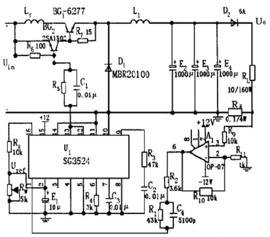
An additional coil is wound on the core of the choke L1 to utilize electromagnetic feedback to reduce the saturation voltage of the switching transistor, and a reasonable structural design is adopted to effectively control the circuit’s distributed parameters. When the power supply voltage decreases or the load resistance RL decreases, the voltage across the sampling resistor RS will also decrease, causing the duty cycle of the square wave output from pins 12 and 13 of the SG3524 to increase, thereby extending the conduction time of BG1 and restoring the voltage U0 to its original stable value. After BG1 is turned off, the energy storage components L1, E2, E3, and E4 ensure that the voltage across the load remains unchanged. When the input power supply voltage increases or the load resistance increases, causing U0 to increase, the principle is similar, and the circuit uses a closed-loop feedback system to bring U0 back down to its original stable value, thereby achieving stable load current IL.
Switching Constant Current Source Using Integrated Voltage Regulators
The circuit configuration of the switching constant current source using integrated voltage regulators is shown in the figure. MC7805 is a three-terminal fixed integrated voltage regulator, RL is the load resistor, and RW is an adjustable resistor. The working principle: the fixed integrated voltage regulator operates in a floating state, with a potentiometer RW connected between output terminal 2 and common terminal 3, forming a fixed constant current source. By adjusting RW, the current can be varied, with the output current given by: IL = (Uout/RW) + Iq, where Iq is the static current of the MC7805, which is less than 10mA. When RW is small, i.e., when the output current is large, Iq can be ignored. When the load resistance RL changes, the MC7805 maintains the current through the load by changing its own voltage drop.
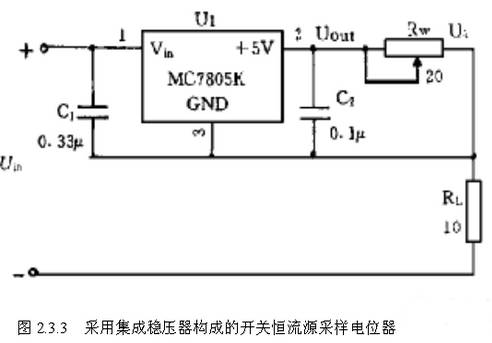
The value of RW can be determined by RW = Uout/IL. Given Uout = 5V and IL = 0.5 to 2A, the determined range is 2.5 to 10Ω. The determination of the output voltage and load variation range: according to design requirements, the output voltage U0 = 10V. Since the adjustable output current range of the constant current source is 0.5 to 2A, the corresponding load variation range is 5 to 20Ω. The above several constant current source structures are simple, highly reliable, and easy to adjust, and have been applied in scientific research. Among them, the linear constant current source is suitable for constant current discharge of batteries, the switching constant current source is suitable for constant current charging of batteries, and the constant current source using integrated voltage regulators is suitable for resistance measurement, etc.
Voltage-Controlled Constant Current Source Circuit Design
The voltage-controlled constant current source is an important component of the system, and its function is to control the change of current using voltage. Due to the high requirements of the system for the output current magnitude and precision, selecting a suitable voltage-controlled constant current source circuit is particularly important. The circuit schematic is shown in Figure 2.4.3. This constant current source circuit consists of an operational amplifier, a high-power field-effect transistor Q1, a sampling resistor R2, and a load resistor RL, etc.
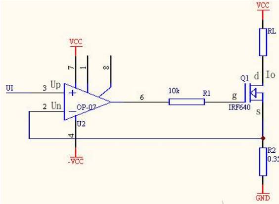
In the circuit, the adjustment transistor is a high-power field-effect transistor IRF640. Using a field-effect transistor makes it easier to achieve voltage linear control of current, meeting the requirement for maximum output current of 2A while also achieving a relatively linear control of current with respect to voltage. When the field-effect transistor operates in the saturation region, the drain current Id is approximately controlled by the gate-source voltage Ugs. That is, when Ud is constant, it satisfies: Id = f(Ugs). As long as Ugs remains unchanged, Id remains unchanged. In this circuit, R2 is the sampling resistor, made of constantan wire (which has a low temperature coefficient), with a resistance value of 0.35 ohms. The operational amplifier OP-07 is used as a voltage follower, UI = Up = Un, and the field-effect transistor Id = Is (the gate current is relatively small and can be ignored), so Io = Is = Un/R2 = UI/R2. Because Io = UI/R2, the input voltage UI controls the current Io, meaning Io does not change with RL, thus achieving voltage-controlled constant current. Simultaneously, from design requirements, it is known that due to the output voltage variation range U ≤ 10V, Iomax = 2A, the maximum load resistance RLmax = 5 ohms can be derived.
Power Supply Circuit Design
This system has high requirements for the power supply. When designing the power supply, it is necessary to ensure high stability and that the power supply can output a current greater than 2A. Therefore, this system uses a three-stage transistor 1264 to expand the current, and the efficiency of the power supply must be fully considered during use. The power supply circuit is shown in the figure, which uses LM317 and LM337, with continuously adjustable output voltages set to +15V and -15V for the hardware circuit. The -15V power supply is used for operational amplifiers and does not require current expansion, while the +15V power supply has a load current requirement of no less than 2A, so a three-stage 1264 is used for current expansion. Additionally, LM7805 is used to generate +5V for the Lingyang SPCE061A microcontroller.

Linear constant current sources and switching constant current sources are highly reliable and easy to adjust, and have been applied in scientific research. Among them, the linear constant current source is suitable for constant current discharge of batteries, the switching constant current source is suitable for constant current charging of batteries, and the constant current source using integrated voltage regulators is suitable for resistance measurement, etc. The SPCE061A microcontroller serves as the central controller, and this system features strong functionality, reliable performance, compact size, and simple circuitry. The system can step as low as 1mA, with relatively high precision. The output current range is quite broad, and the thermal stability of the sampling resistor in the hardware part must be good. The core module in the hardware is the voltage-controlled constant current source, with the core component being a field-effect transistor, which has superior performance and stability compared to bipolar transistors.