How to determineif a Modbus TCPconnection is established?
Answer: To performModbus TCPcommunication, a connection must be established.
S7-200 SMART CPUas aModbus TCPclient: You can determine the connection status using the Modbus TCP Client instruction’s symbol table parameter mConnected, as shown in Figure 1. If mConnected=1, it indicates that the connection has been established, while mConnected=0 indicates that the connection has not yet been established.
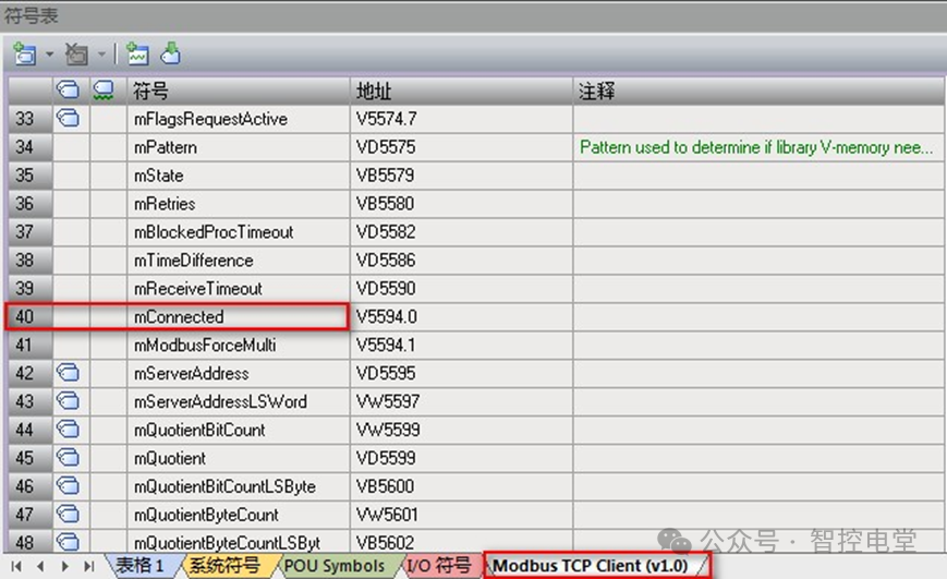
Figure 1. mConnected to determine connection status
S7-200 SMART CPUas aModbus TCPserver: You can determine the connection status using the Modbus TCP Server instruction’s symbol table parameter mConnected, as shown in Figure 2.
If mConnected=1, it indicates that the connection has been established, while mConnected=0 indicates that the connection has not yet been established..
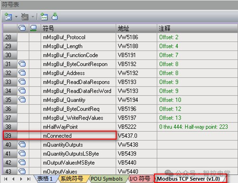
Figure 2. mConnected to determine connection status
Note: When there are multiple clients or servers in the PLC, it is not recommended to rely on this status point.
2 How to view error codes?
Answer: When an error occurs, the MBUS_CLIENT instruction’s output parameter Done will be set to 1, but Done will also be set to 1 when the connection is established, disconnected, or when a response is completed. When an error occurs, the Error byte will display the error code, but it will only be retained for one cycle. Therefore, to view the error code, you can follow the method shown in Figure 3.
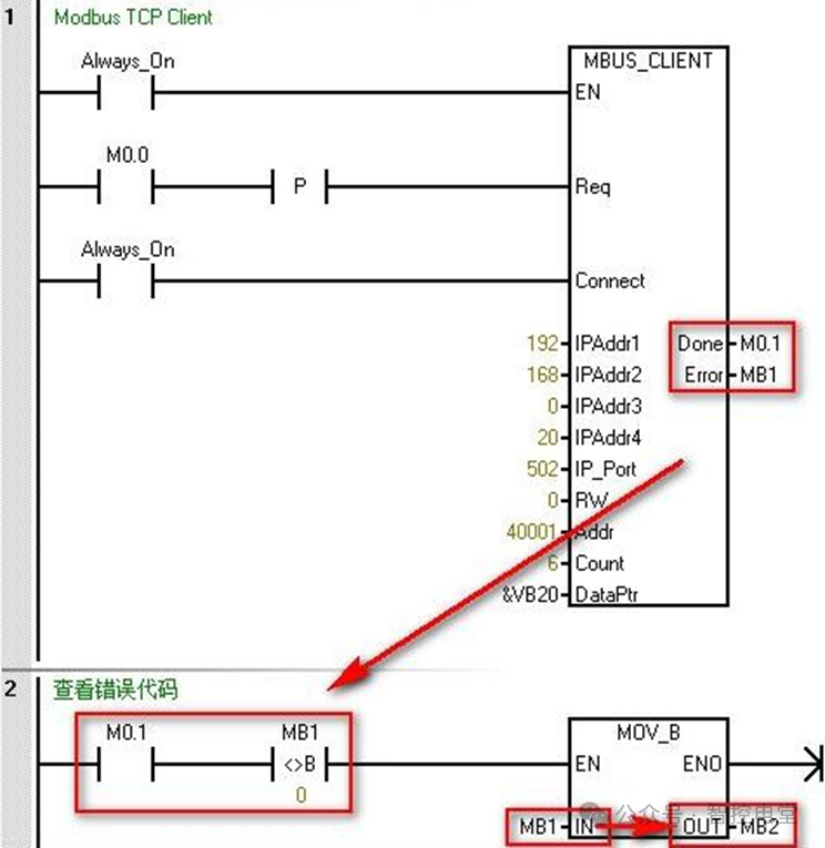
Figure 3. View error codes
3 How to handle Modbus TCP communication with register type data exceeding 120 words?
Answer: If the data volume exceeds 120 words, you can perform the following two methods:
A Establish multiple connections; different connections can operate in parallel because they occupy different communication resources;
B Establish a single connection and perform multiple operations; different operations need to be polled, and only one operation can be performed at a time.
4 How to access holding registers with addresses greater than 49999 during Modbus TCP communication?
Modbus holding register addresses range from 40001 to 49999, which is sufficient for most applications. However, some Modbus slave devices map data to holding registers with larger address ranges. The MBUS_CLIENT instruction allows for an additional range in the Addr parameter to support 400001 to 465536 holding register addresses. For example, to access holding register 16768, set the MBUS_CLIENT Addr parameter to 416768. Extended addressing allows access to all 65536 possible addresses supported by the Modbus protocol. This extended addressing is only applicable to holding registers.
5 How to distinguish Modbus RTU slave addresses when S7-200 SMART acts as a Modbus TCP client, and the server is a gateway module connecting multiple Modbus RTU devices?
Answer: The S7-200 SMART CPU acts as a Modbus TCP client communicating with the Modbus TCP server. When attempting to access devices in a lower-end serial subnet than the Modbus TCP server, an error will occur: “Unable to establish connection”. If the Modbus TCP server is used as a gateway for the Modbus RTU protocol, the MB_UNIT_ID can be used to identify the slave devices connected on the serial network. The MB_UNIT_ID is used to forward requests to the correct Modbus RTU slave address. Some Modbus TCP devices may require the MB_UNIT_ID parameter to be within a limited range. The location of this parameter is shown in Figure 4. The default value of mModbusUnitID is 255 (16#FF). If there are multiple slave devices, you can establish a connection between the S7-200 SMART and the gateway module, and modify the value of UnitID for polling.
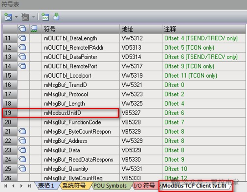
Figure 4. mModbusUnitID
6 For some servers that do not support writing a single digital output bit (function code 5)/ a single holding register (function code 6), how to implement writing a single bit/ word with S7-200 SMART?
Answer: Some Modbus server devices do not support Modbus functions for writing a single discrete output bit (Modbus function 5) or writing a single holding register (Modbus function 6). Instead, these devices only support multi-bit writing (Modbus function 15) or multi-register writing (Modbus function 16). If the server device does not support single bit/ word Modbus functions, the MBUS_CLIENT instruction will return error code 1. The Modbus client protocol allows forcing the MBUS_CLIENT instruction to use multiple bits/ words Modbus functions instead of using single bits/ words Modbus functions. This can be done by looking up the symbol mModbusForceMulti in the Modbus client symbol table and changing this value before executing the MBUS_CLIENT instruction to force multiple bits/ words instructions. Setting mModbusForceMulti to TRUE will force the use of multiple bits/ words functions when writing a single bit or register. As shown in Figure 5.
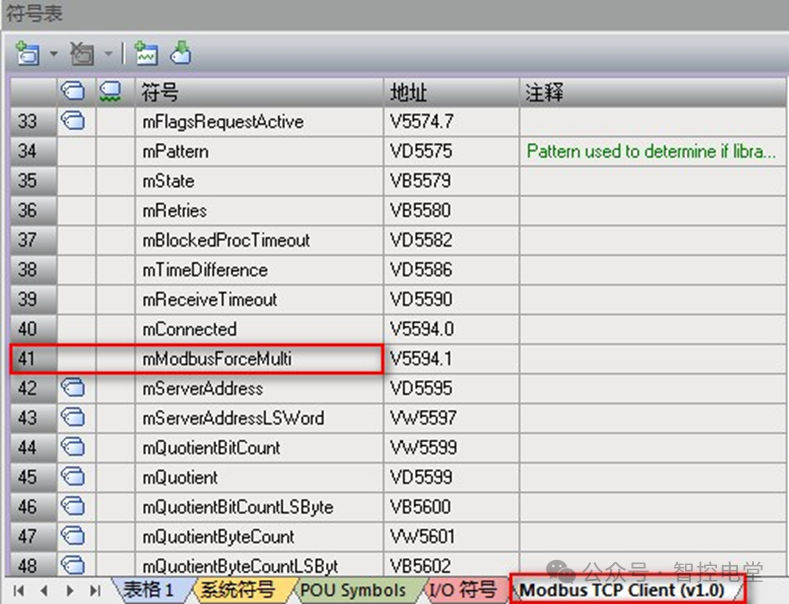
Figure 5. mModbusForceMulti
Previous Recommendations
Programming tips for delay issues in PLC positioning control, a must-read!
[Essential for Beginners] Understanding number base conversion in PLC
Siemens launches the new S7-200 SMART V3.0
S7-200 SMART achieves speed control through PN connection with V90 PN using message 1 and SINA_SPEED function block
How to simulate in TIA PORTAL version 18 and above?
Must-know issues regarding S7-1200 To zero return and axis-related problems
There is always a software you need, check it out!
This method permanently solves the timestamp mismatch issue in SMART
S7-1200 achieves position control of V90 PN through TO
Q&A | How to find the GSD files already installed in the project?
[Must-read for Newbies] How to restore the initialization interface after EPLAN misoperation?
How to encapsulate a motion axis function block
Experiencing MODBUS communication issues? The debugging assistant can help!