Modbus Communication Protocol
History
Initially, factories controlled systems through what was known as large microprocessor systems in “Distributed Control Systems” or “DCS”. A central control system managed the entire setup (in the control room). All sensors and actuators were connected to the control system via point-to-point wiring. Alternatively, they could be added in a network topology.
To reduce costs, Modicon (the predecessor of Schneider’s large PLC) invented the most complete Programmable Logic Controller (PLC).
Since PLCs need to share data, Modicon created a communication protocol in 1979: Modicon + fieldbus = MODBUS
Basics of Modbus Protocol
There are different types of Modbus protocols (MODBUS ASCII, Modbus RTU, MODBUS TCP/IP, Modbus Plus, Modbus Pemex…)
This training document mainly covers RTU and TCP/IP.
Classification of Modbus
One mode is ASCII (American Standard Code for Information Interchange),
the other mode is RTU (Remote Terminal Unit).
The most commonly used serial protocol by Schneider Electric is Modbus RTU.
Common serial devices for Modbus RTU include: RS232, RS422, RS485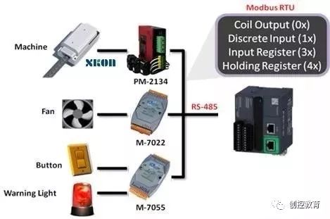
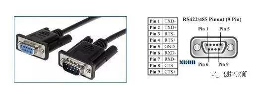
RS232
RS-232 is an asynchronous transmission standard interface defined by the Electronic Industries Association (EIA). Typically, the RS-232 interface appears in 9-pin (DB-9) or 25-pin (DB-25) forms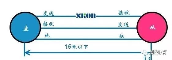
The main disadvantage of RS232 is that it can only communicate point-to-point.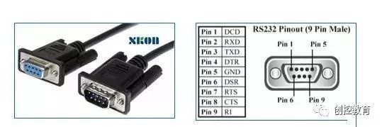
The maximum transmission speed is 10 Mbps.
The theoretical length of the cable is 15 meters. In practice, by using high-quality cables, it is possible to exceed this length. Simply using shielded cables (ordinary or better twisted pairs) can extend the distance between communication parties to 25-30 meters.
RS422
RS-422 (EIA RS-422-A standard) was historically used for serial connections in Apple Macintosh computers. RS-422 uses differential electrical signals, unlike RS-232 which uses unbalanced signals relative to ground. Differential transmission sends and receives signals using two wires, providing better noise immunity and longer distance signals. These advantages make RS-422 more suitable for industrial applications.
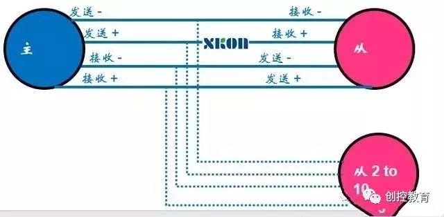
Due to the receiver’s high input impedance and the transmitter’s stronger driving capability compared to RS232, it allows for a maximum of 10 nodes. That is, one master device (master) and multiple slave devices (slaves), with no communication between slaves, supporting point-to-multipoint bidirectional communication. The maximum transmission rate is 10 Mbps.
Relationship Between Communication Line Length and Maximum Speed
12m = 10 Mbps
120m = 1 Mbps
1200m = 100 kbps
RS485
RS485 standard is defined by the Telecommunications Industry Association and the Electronic Industries Alliance. Digital communication networks using this standard can effectively transmit signals over long distances and in environments with high electronic noise. RS-485 enables the configuration of inexpensive local networks and multi-branch communication links.
RS485 is now mostly adopted in a two-wire connection method, which forms a bus topology, requiring only two data lines and one ground line.
For communication between a master and multiple slave devices, RS485 is currently the most popular method. Without repeaters, it can support up to 32 nodes, with a length of about 1200 meters.
A serial Modbus network has one master device and multiple slave devices, and the communication is half-duplex.
In the absence of repeaters, a maximum of 32 stations per segment is allowed.
In harsh environments, armored twisted shielded cables should also be used
In RS485 communication networks, the master-slave communication method is generally adopted, meaning one master with multiple slaves. In many cases, connecting RS-485 communication links simply involves connecting the “A” and “B” ends of each interface with a pair of twisted wires while neglecting the connection of the signal ground. This connection method can work properly in many cases but poses significant risks. Reason 1 is common-mode interference: RS-485 interfaces use differential transmission methods and do not require a reference point to detect signals; the system only needs to detect the potential difference between the two wires, but it is easy to overlook that transceivers have a certain common-mode voltage range. The common-mode voltage range for RS-485 transceivers is -7 to +12V. Only by meeting the above conditions can the entire network operate correctly; when the common-mode voltage in the network exceeds this range, it can affect the stability and reliability of communication, and even damage the interface. Reason 2 is the EMI issue: the common-mode part of the signal output by the transmitting driver requires a return path; if there is no low-resistance return path (signal ground), it will return to the source in the form of radiation, making the entire bus act like a huge antenna radiating electromagnetic waves.
Terminal Resistance and Polarization Resistance of RS485
It is recommended to add terminal resistors of 120 ohms and 1nF at both ends of the communication network to ensure impedance matching.
Polarization resistors are added on the master side to effectively improve the master’s ability to drive slaves, typically used when there are many slaves.
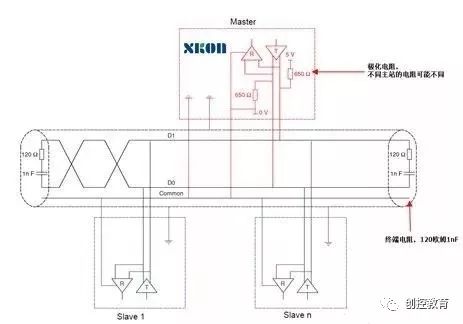
In cases with fewer devices and short distances, the entire network can work well without adding terminal load resistors, but performance will decrease as distance increases. Theoretically, when sampling at the midpoint of each received data signal, as long as the reflected signal attenuates to a sufficiently low level by the time sampling begins, matching can be disregarded. However, this is difficult to manage in practice. An article by MAXIM in the USA mentions an empirical principle that can be used to determine when matching is needed based on the data rate and cable length: when the signal transition time (rise or fall time) exceeds three times the time required for a signal to travel one way along the bus, matching can be omitted.
Generally, terminal matching is done using terminal resistors; RS-485 should connect terminal resistors at both the start and end of the bus cable. The terminal resistance in an RS-485 network is set to 120Ω, which corresponds to the characteristic impedance of the cable, as most twisted pair cables have a characteristic impedance of about 100-120Ω. This matching method is simple and effective, but it has a drawback: the matching resistors consume a significant amount of power, making it unsuitable for systems with strict power consumption limits. Another more power-saving matching method is RC matching, which uses a capacitor C to block the DC component, saving most of the power.
RS485 Serial Port Configuration
Each device on the RS485 bus needs to configure some parameters; TM241 uses SoMachine for configuration, while TM221 requires the use of SoMachine Basic software.
The Modbus slave address cannot be duplicated on the same bus; for some slave devices such as frequency converters ATV320, 340, servo, etc., it is also required to power them off and back on after modification!
All devices on the RS485 bus must have the same baud rate, data bits, stop bits, and parity method!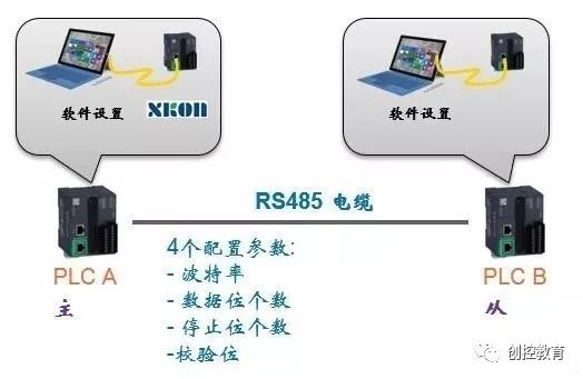
The baud rate refers to the number of times the carrier parameters change in a unit of time; for example, if 240 characters are transmitted per second and each character format contains 10 bits (1 start bit, 1 stop bit, 8 data bits), then the baud rate is 240Bd, and the bit rate is 10 bits * 240 characters/second = 2400bps.
The data bits refer to the parameters of the actual data bits in communication, with standard values being 5, 6, 7, and 8 bits. RTU is automatically set to 8 bits, while other settings are for ASCII code usage.
The stop bit is used to indicate the last bit of a single packet. Typical values are 1, 1.5, and 2 bits. Stop bits.
The parity bit is a simple error-checking method in serial communication. There are four error-checking methods: even, odd, high, and low. It is also acceptable to have no parity bit.
Modbus Data Frame Format
MODBUS protocol defines a simple Protocol Data Unit (PDU) that is independent of the underlying communication layer. The MODBUS protocol mapping on a specific bus or network can introduce some additional fields in the Application Data Unit (ADU).
Address Code: The first byte, each slave has a unique address code, and the response begins with its own address code. The address code sent by the master indicates the address of the slave to which it will send, while the address code sent by the slave indicates the address of the slave responding. An address code of 0 indicates broadcast mode.
Function Code: The second byte of communication transmission. As a request sent by the master, the function code tells the slave what action to perform. As a response from the slave, the function code sent by the slave is the same as that sent by the master, indicating that the slave has responded to the master’s operation. If the highest bit of the function code sent by the slave is 1 (for example, if the function code is greater than or equal to 127), it indicates that the slave did not respond or an error occurred.
Data Area: The data area varies depending on the function code. The data area can be actual values, set points, or addresses sent from the master to the slave or from the slave to the master.
Error Check: Uses CRC code, which is a two-byte error detection code.
Modbus Addresses and Values
All electronic devices have internal storage areas for storing different types of data. It was originally developed for PLCs to communicate with other devices via Modbus. In general, four types of connections are used for sensors and actuators.
PLCs need to store data for operation.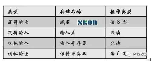
Each storage area stores different values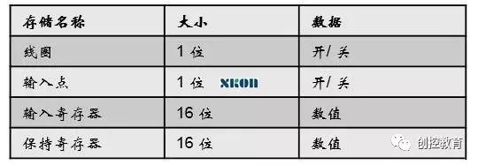
Modbus Function Codes
Function Code: The function code sent by the master tells the slave what task to perform.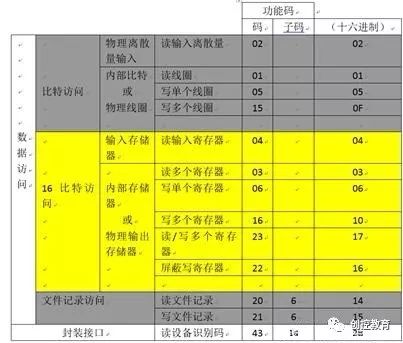
Modbus Check Code
Check Code: Modbus communication uses CRC-16 cyclic redundancy check, which includes 2 bytes, i.e., 16 bits.
The CRC calculation method is:
1. Load a value of 0XFFFF into a 16-bit register, which serves as the CRC register.
2. XOR the first 8-bit binary data (the first byte of the communication information frame) with the 16-bit CRC register, and store the result back in the CRC register.
3. Right shift the contents of the CRC register by one, filling the highest bit with 0, and check whether the shifted-out bit is 0 or 1.
4. If the shifted-out bit is zero, repeat step 3 (right shift again); if the shifted-out bit is 1, XOR the CRC register with 0XA001.
5. Repeat steps 3 and 4 until right shifting 8 times, processing all 8-bit data.
6. Repeat steps 2 and 5 to process the next byte of the communication information frame.
7. After processing all bytes of the communication information frame as described above, swap the high and low bytes of the resulting 16-bit CRC register.
8. The final content of the CRC register is the CRC check code.
(Content from the internet, copyright belongs to the original author)
Disclaimer:If there are any copyright issues, please contact for deletion!
No person or organization assumes related legal responsibilities.
Recommended Reading:
Benefits Arrive!Free Learning of Schneider SoMachine Detailed Course
2019 Industrial Automation Employment Trends, Comprehensive Analysis of Domestic Colleges
The first batch of IAAT certificates has been issued, please check, engineers!
Summary of RS485 and Modbus Communication Protocols, everything you want is here!
For detailed course inquiries:
Teacher Cheng 15315136942 (WeChat same number)
Technical communication group:536682860 (QQ group)