Previously, we discussed the hardware form and basic principles of JTAG. This article uses a JTAG VIP simulation to interpret the waveforms.
Referencing SOC Design (4) – Using S Company’s VIP, we first generate an example for JTAG testing:
dw_vip_setup -path /home/designware/run_jtag -example jtag_svt/tb_jtag_svt_uvm_basic_sys
Enter the simulation directory with cd run_jtag/examples/sverilog/jtag_svt/tb_jtag_svt_uvm_basic_sys, and type in:
gmake USE_SIMULATOR=vcsvlog WAVES=fsdb arm_directed_test1
This will complete a simulation. Similarly, using logs/compile.log we can obtain the following file list:
+incdir+/home/designware/run_jtag/src/sverilog/vcs+incdir+/home/designware/run_jtag/include/sverilog+incdir+/home/designware/run_jtag/src/verilog/vcs+incdir+/home/designware/run_jtag/include/verilog+incdir+/usr/Synopsys/vcs/T-2022.06/etc/uvm-1.2/src+incdir+/home/designware/run_jtag/examples/sverilog/jtag_svt/tb_jtag_svt_uvm_basic_sys/.+incdir+/home/designware/run_jtag/examples/sverilog/jtag_svt/tb_jtag_svt_uvm_basic_sys/../../env+incdir+/home/designware/run_jtag/examples/sverilog/jtag_svt/tb_jtag_svt_uvm_basic_sys/../env+incdir+/home/designware/run_jtag/examples/sverilog/jtag_svt/tb_jtag_svt_uvm_basic_sys/env+incdir+/home/designware/run_jtag/examples/sverilog/jtag_svt/tb_jtag_svt_uvm_basic_sys/dut+incdir+/home/designware/run_jtag/examples/sverilog/jtag_svt/tb_jtag_svt_uvm_basic_sys/hdl_interconnect+incdir+/home/designware/run_jtag/examples/sverilog/jtag_svt/tb_jtag_svt_uvm_basic_sys/lib+incdir+/home/designware/run_jtag/examples/sverilog/jtag_svt/tb_jtag_svt_uvm_basic_sys/tests/home/designware/run_jtag/examples/sverilog/jtag_svt/tb_jtag_svt_uvm_basic_sys/top.sv
The file list mainly includes top.sv and several include files. Use the following command to open Verdi and view the relevant signals:
verdi -top test_top -f verdi_files -sv -ssf test_top.fsdb &
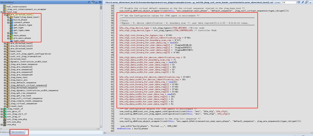
As shown in Figure 1, we can view the test arm_directed_test1 from Verdi’s Declaration window.
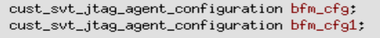
We can see that the test is configured with two devices, bfm_cfg and bfm_cfg1, which are the driver and Controller, respectively. These two devices are defined in jtag_base_test.sv, as shown in Figure 2:
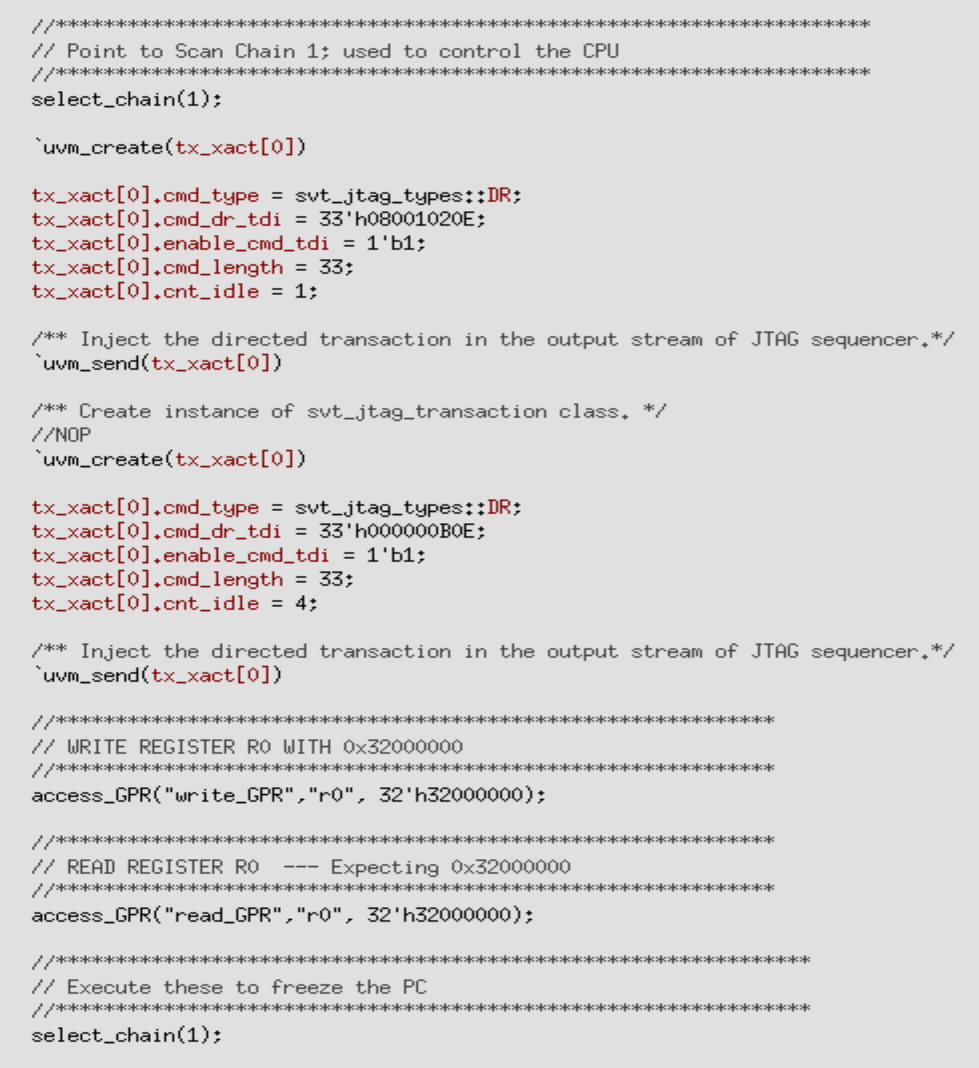
The final simulation execution operations are in jtag_arm_sequence.sv, as shown in Figure 3:
To see the execution of the TAP controller more clearly, we connect a real ARM code containing the TAP controller as a slave. Modify hdl_files and simultaneously modify top.sv to instantiate the ARM, ensuring the port is set to JTAG mode.
Let’s take a look at the above commands:
virtual task select_chain(bit[31:0] chain); `uvm_create(tx_xact[0]) // Update instruction register to SCAN_N `uvm_info($sformatf("select_chain %0h", chain), "Update instruction register: SCAN_N", UVM_LOW) `uvm_info($sformatf("select_chain %0h", chain), "IR = SCAN_N", UVM_LOW) tx_xact[0].cmd_type = svt_jtag_types::IR; tx_xact[0].cmd_ir_tdi = `JtagCmdSCAN_N; `uvm_send(tx_xact[0]) `uvm_create(tx_xact[0]) // Select scan chain N (Embedded-ICE RT) tx_xact[0].cmd_type = svt_jtag_types::DR; tx_xact[0].cmd_dr_tdi = chain; tx_xact[0].cmd_length = 5; tx_xact[0].cnt_idle = 0; `uvm_send(tx_xact[0]) `uvm_create(tx_xact[0]) // Drive INTEST to instruction register `uvm_info($sformatf("select_chain %0h", chain), "IR = INTEST", UVM_LOW) tx_xact[0].cmd_type = svt_jtag_types::IR; tx_xact[0].cmd_ir_tdi = `JtagCmdINTEST; `uvm_send(tx_xact[0]) endtask // select_chain
The above select_chain command includes the uvm_create macro to create a tx_xact object, then assigns values to the object and sends it out using the uvm_send macro. Let’s look at the uvm_send macro; you can see the specific content of the macro in Verdi, or type in the following command:
cd $UVM_HOMEgrep -r "uvm_send_pri"
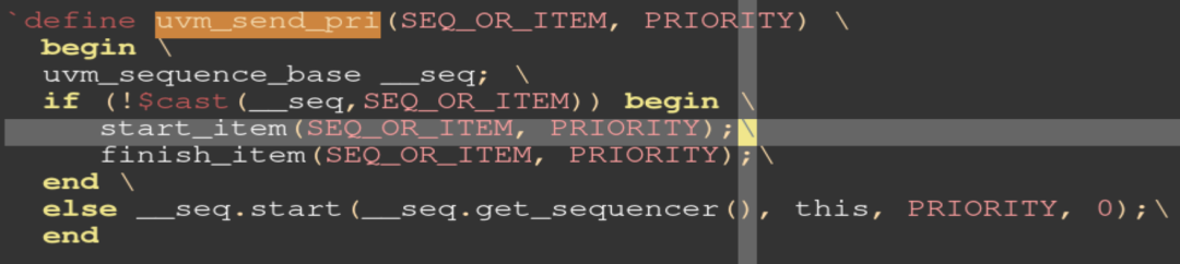
You can see that uvm_send_pri is in the macros/uvm_sequence_defines.svh file, as shown in Figure 4:
Essentially, it sends out the sequence item created by uvm_create.
The specific contents of the item are printed in logs/simulate__arm_directed_test1.log, with the first sent item as follows:
tx_xact[0] cust_svt_jtag_transaction - @2008 causal_xact object - <null> implementation da(object) 0 - original_xact object - <null> trace da(object) 0 - cfg object - <null> exception_list object - <null> capture_boundary_scan_reg integral 32 'h1 accept_time time 64 60000 begin_time time 64 60000 depth int 32 'd2 parent sequence (name) string 18 jtag_arm_sequence1 parent sequence (full name) string 63 uvm_test_top.env.agent_bfm0.transaction_seqr.jtag_arm_sequence1 sequencer string 44 uvm_test_top.env.agent_bfm0.transaction_seqr cmd_type cmd_type_enum 32 IR cmd_length integral 32 'd16 cmd_ir_tdi integral 16 'h2 cmd_dr_tdi integral 67 'h0 cnt_idle integral 32 'd3 enable_cmd_tdi integral 1 'd1 user_tdi da(integral) 0 - user_tms da(integral) 0 -
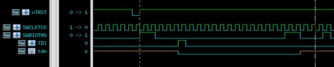
The first entry of the select_chain corresponds to the waveform shown in Figure 5:
This is also reflected in the log, as shown in Figure 6:
Open the state machine code controlled by TMS, as follows:
always @(jtag_state or tms) case (jtag_state) JTAG_TLR : jtag_state_next = (tms ? JTAG_TLR : JTAG_RTI); JTAG_RTI : jtag_state_next = (tms ? JTAG_SDS : JTAG_RTI); //DR States JTAG_SDS : jtag_state_next = (tms ? JTAG_SIS : JTAG_CDR); JTAG_CDR : jtag_state_next = (tms ? JTAG_E1D : JTAG_SDR); JTAG_SDR : jtag_state_next = (tms ? JTAG_E1D : JTAG_SDR); JTAG_E1D : jtag_state_next = (tms ? JTAG_UDR : JTAG_PDR); JTAG_PDR : jtag_state_next = (tms ? JTAG_E2D : JTAG_PDR); JTAG_E2D : jtag_state_next = (tms ? JTAG_UDR : JTAG_SDR); JTAG_UDR : jtag_state_next = (tms ? JTAG_SDS : JTAG_RTI); //IR States JTAG_SIS : jtag_state_next = (tms ? JTAG_TLR : JTAG_CIR); JTAG_CIR : jtag_state_next = (tms ? JTAG_E1I : JTAG_SIR); JTAG_SIR : jtag_state_next = (tms ? JTAG_E1I : JTAG_SIR); JTAG_E1I : jtag_state_next = (tms ? JTAG_UIR : JTAG_PIR); JTAG_PIR : jtag_state_next = (tms ? JTAG_E2I : JTAG_PIR); JTAG_E2I : jtag_state_next = (tms ? JTAG_UIR : JTAG_SIR); JTAG_UIR : jtag_state_next = (tms ? JTAG_SDS : JTAG_RTI); default : jtag_state_next = 4'bxxxx; endcase
The state machine is defined as follows:
localparam [3:0] JTAG_TLR = 4'b1111; //Test Logic Resetlocalparam [3:0] JTAG_RTI = 4'b1100; //Run-Test/Idlelocalparam [3:0] JTAG_SDS = 4'b0111; //Select-DR-Scanlocalparam [3:0] JTAG_CDR = 4'b0110; //Capture-DRlocalparam [3:0] JTAG_SDR = 4'b0010; //Shift-DRlocalparam [3:0] JTAG_E1D = 4'b0001; //Exit1-DRlocalparam [3:0] JTAG_PDR = 4'b0011; //Pause-DRlocalparam [3:0] JTAG_E2D = 4'b0000; //Exit2-DRlocalparam [3:0] JTAG_UDR = 4'b0101; //Update-DRlocalparam [3:0] JTAG_SIS = 4'b0100; //Select-IR-Scanlocalparam [3:0] JTAG_CIR = 4'b1110; //Capture-IRlocalparam [3:0] JTAG_SIR = 4'b1010; //Shift-IRlocalparam [3:0] JTAG_E1I = 4'b1001; //Exit1-IRlocalparam [3:0] JTAG_PIR = 4'b1011; //Pause-IRlocalparam [3:0] JTAG_E2I = 4'b1000; //Exit2-IRlocalparam [3:0] JTAG_UIR = 4'b1101; //Update-IR
It can be seen that JTAG operations are divided into two steps:
Step 1: The serial input TMS signal determines the current state of the controller.
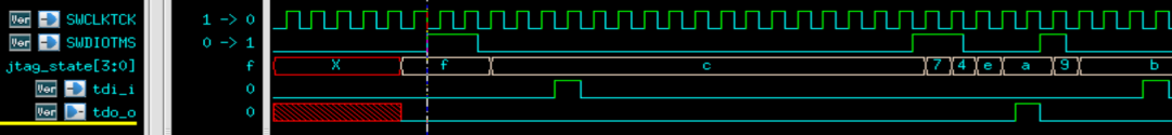
Step 2: Based on the controller state, the TDI input and TDO output are determined, as shown in Figure 8:
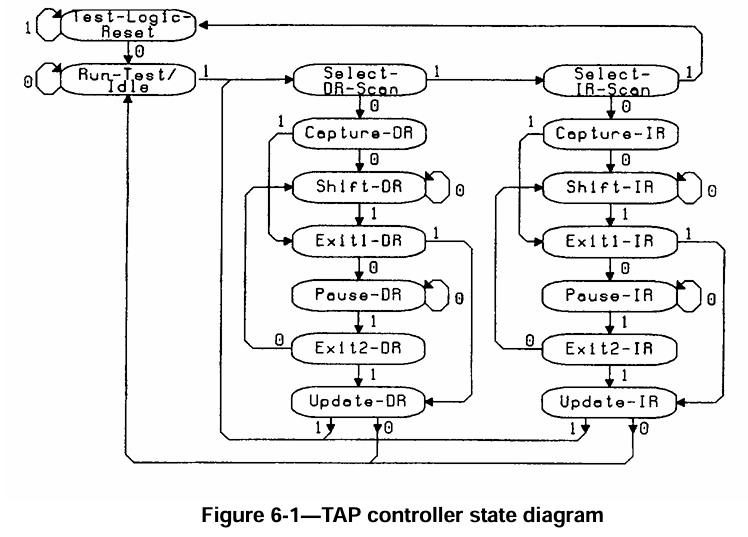
We can compare this with the state machine in IEEE-Std-1149.1-2001, as shown in Figure 9:
It can be seen that there are a total of 16 states. After power-up reset, it enters Test-Logic_Reset; after that, when TMS equals 0, it enters Run-Test_Idle; when TMS equals 1, it enters Select-DR-Scan, matching the previous code. With this foundation, we can explore the specific implementation details of each state machine ourselves, and will not elaborate further here.
This concludes the article. If you like this article, feel free to follow and share it. More content will be brought to you later.