Power Hardware-in-the-Loop (PHIL) testing combines real-time simulators, power amplifiers, and the devices under test to achieve the extension of signal-level real-time simulation to power-level applications. It can be used to test real power devices such as energy storage devices, photovoltaic devices, and wind turbines, featuring flexible system topology changes and the ability to simulate various grid fault conditions.
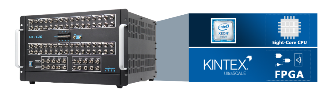
This article will introduce and demonstrate the testing scheme of the power hardware-in-the-loop system based on Yuan Kuan Energy’s MT 8020 real-time simulator.
01
PHIL Topology of Wind and Solar Microgrid and Large Grid
The PHIL structure is shown in the figure below, consisting of the MT 8020 real-time simulator and the microgrid platform. The real-time model of the large grid runs in the HIL real-time simulator. The bus voltage of the large grid is output through the analog IO port of the HIL simulator, and the power amplifier’s output voltage is controlled in real-time using the external input interface. The output of the power amplifier is connected to the AC bus of the microgrid. The current measurement unit collects the current between the microgrid and the power amplifier, then feeds it back to the HIL real-time simulator, associating it with the power of the large grid. This forms a closed-loop real-time simulation structure between a real microgrid and a virtual large grid.
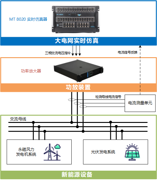
Figure 1.1 PHIL Simulation Topology of Microgrid and Large Grid
02
Introduction to the Large Grid Model
This case uses a 9-node large grid structure, powered by three generators in a ring network, each with a capacity of 200MW and a voltage of 16.7kV, which is then stepped up to 230kV using a transformer. The voltage of the large grid’s ring line is 230kV. This 230kV voltage is then stepped down to 400V through a transformer to provide bus voltage for the microgrid.
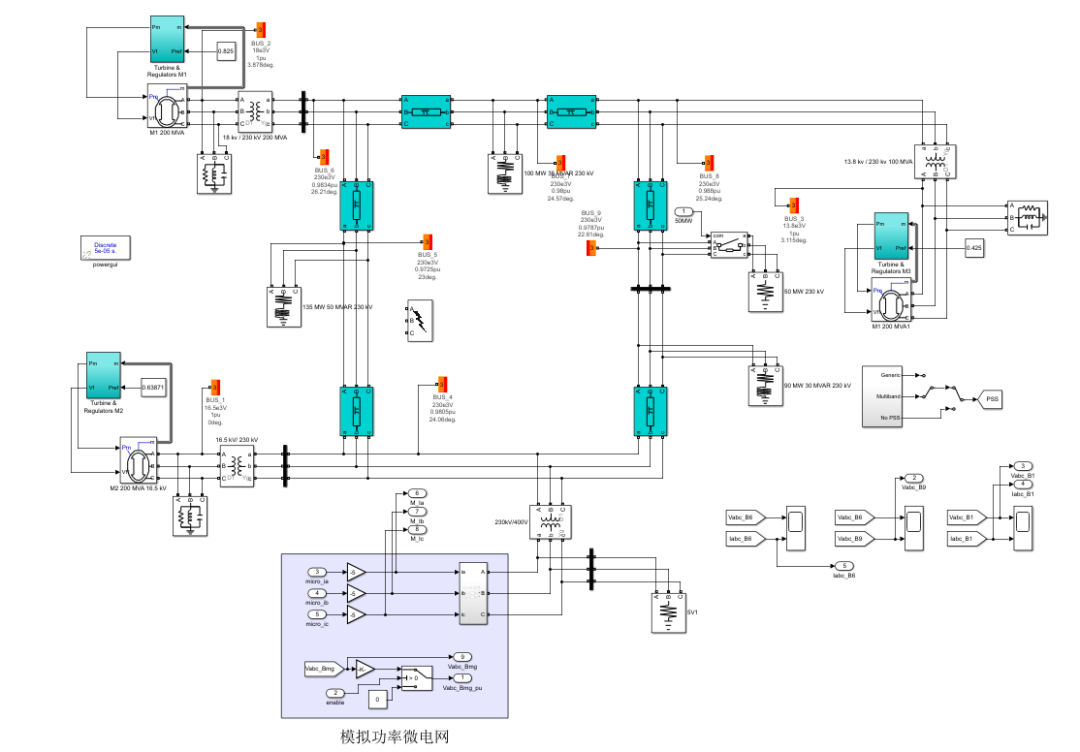
Figure 2.1 Large Grid Simulation Model
03
Introduction to the Wind and Solar Microgrid Experimental Platform
The microgrid experimental demonstration platform consists of a 10kW permanent magnet direct-drive generator system and a 5kW photovoltaic grid-connected system. The power amplifier outputs AC bus voltage, while the MT 8020 HIL real-time simulator runs the large grid model. The real-time simulator forms a closed-loop operating platform with the microgrid platform, constituting the PHIL real-time simulation platform.
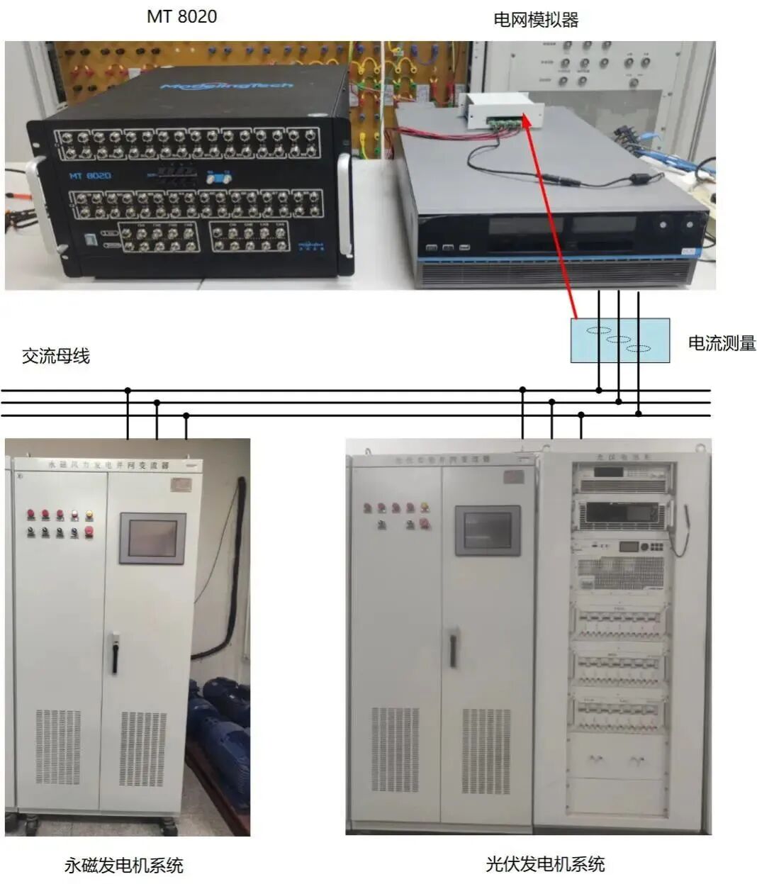
Figure 3.1 Microgrid Experimental Platform
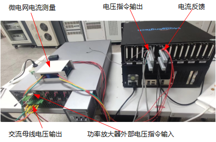
3.2 Wiring Diagram Between Simulator and Power Amplifier
04
Introduction to the PHIL Simulation System
The PHIL real-time simulation monitoring platform is built using HIL upper computer software, as shown in the figure below. It allows observation of the real-time operation of the large grid model and the real-time changes in the microgrid’s energy. It can observe both dynamic performance and steady-state effects.
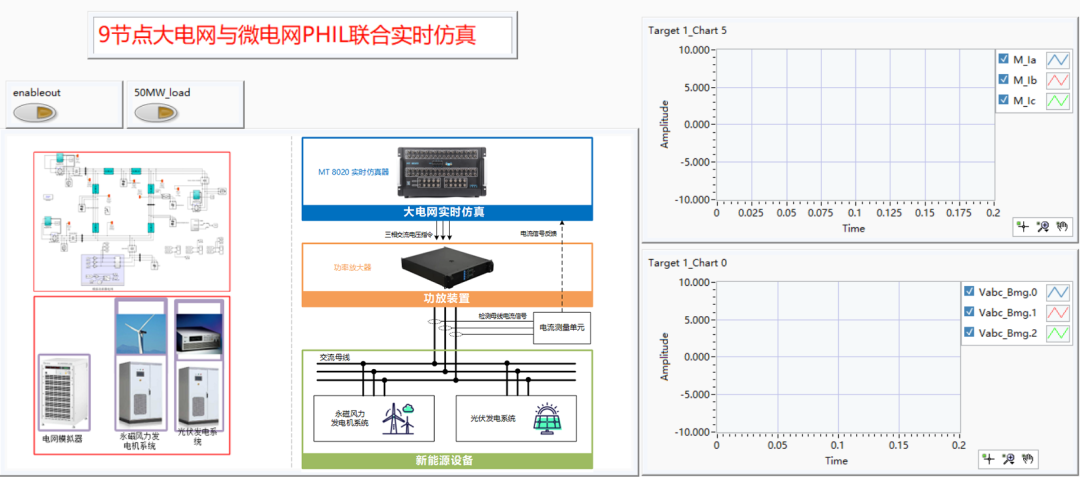
Figure 4.1 PHIL Simulation Upper Computer Interface
05
PHIL Experimental Demonstration
5.1 Large Grid Load Sudden Change Demonstration
When there is a sudden change in the load of the large grid, it causes fluctuations in the bus voltage, and the voltage of the microgrid changes accordingly. The performance of the microgrid during this change can be analyzed and studied. The figure below shows a virtual large grid suddenly increasing by 50MW, causing fluctuations in the bus grid, and the actual voltage changes in the microgrid.

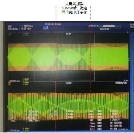
Figure 5.1 Voltage Change Waveform Due to Power Sudden Change in Large Grid
5.2 Microgrid Power Change Demonstration
When the power of the microgrid changes, the PHIL upper computer interface will display the real-time waveform of the energy flow changes between the large grid and the microgrid. Figure 5.2 shows the waveform of the microgrid supplying 5kW to the large grid, and Figure 5.3 shows the process of the wind turbine’s power changing from 5kW to 1kW.
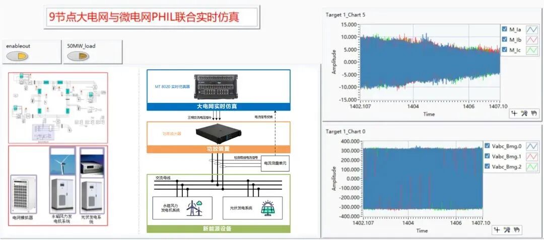
Figure 5.2 Microgrid Wind Turbine Power 5KW Waveform
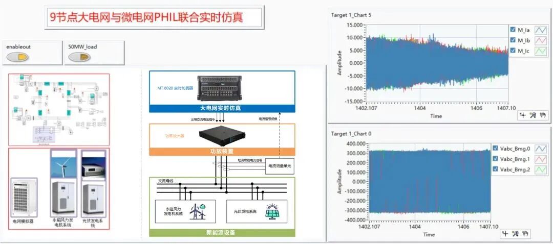
Figure 5.3 Microgrid Wind Turbine Power Change from 5kW to 1kW Waveform
The above microgrid experiment, consisting of the MT 8020 real-time simulator, power amplifier, wind power system equipment, and photovoltaic system equipment, demonstrates that this testing scheme is an important testing approach for researching distributed energy, equipment testing, and grid connection technology.
E
N
D
Contact Information for “Power System Protection and Control”
Website: www.dlbh.net
Editorial Office: 0374-3212254/2234
E-mail: [email protected]
Brand Marketing Department: 0374-3212444
E-mail: [email protected]
Design Department: 0374-3212462
Document Printing Department: 0374-3215923
Distribution Department: 0374-3219411
Official WeChat ID: PSPC-1973
Contact Information for “PCMP”
Website: pcmp.springeropen.com;
www.pcmp.info
E-mail: [email protected]
Official WeChat ID: PSPC-1973