Authors: Gereon Weiss, Marc Zeller, Dirk Eilers and Rudi Knorr
Fraunhofer Institute for Communication Systems ESK,
Hansastr. 32, 80686 Munich, Germany
Original: ceur-ws.org/Vol-644/paper06.pdf
Published in 2010Translation: Joyce Proofreading: MikeThis article is based on the Creative Commons text sharing protocol: https://creativecommons.org/licenses/by-sa/4.0/AbstractThe Architecture Description Language (ADL) allows for the specification of system information within architectural models. These are typically used to capture early design decisions regarding system or software development. Thus, ADL can be used for modeling early and iterative validation of systems. Using EAST-ADL defines automotive-specific ADL, allowing for the description of automotive systems at different abstraction layers targeting AUTOSAR systems. SystemC is an executable system modeling and simulation language that allows hardware/software co-design. Using Transaction Level Modeling (TLM) methods, descriptions of different abstraction layers can be realized in SystemC. This work addresses the early validation of automotive electronic systems by providing a transformation of EAST-ADL models at different abstraction layers to SystemC. This allows for iterative analysis using hardware/software co-simulation during the development process. The proposed method is implemented in a toolchain and demonstrated through typical automotive use cases. Therefore, we show the potential of early validation of system and software design based on architectural models.1 IntroductionModel-driven design has been successfully introduced in various application domains to abstract from complex systems. Using Architecture Description Language (ADL) provides a solution to capture high-level design information [1]. Various model-based tools exist that can model different behaviors of functionalities. ADL allows for modeling interactions of these functionalities at the system level describing software and system architecture. Explicit modeling of the system abstraction layers provides the possibility to abstract the system implementation from different perspectives. Therefore, specific details of particular interest can be focused on specific levels. Since architectural models contain system information, they can be used for architectural validation even at early design stages. Approaches that are well integrated with tool flows can validate iteratively as the system matures. This allows for early feedback to developers and avoids changes due to design issues discovered later.The automotive domain is a field with complex interconnected embedded systems. Domain-specific modeling languages have been introduced to realize different functional behaviors. Since this alleviates the development of individual applications, a coarser-grained view of the entire system is required as the more interactive functionalities exist. EAST-ADL [2] serves as a system-level view in the automotive domain, allowing for abstraction from different levels of automotive electronic systems. At the implementation level, the Automotive Open System Architecture (AUTOSAR) [3] meta-model is adopted to enable the realization of a well-defined integration in current development approaches. For the simulation and validation of hardware/software systems, the system modeling language SystemC [4] has been developed. It includes a simulation kernel and structures for hardware/software co-design. Using Transaction Level Modeling (TLM) [5], different levels of abstraction can be modeled in SystemC. Furthermore, a subset of SystemC is synthesizable, for instance, for FPGA implementations.Since using SystemC for simulation-based validation of automotive electronic systems is a promising design exploration and hardware prototyping method, it must be integrated into architectural design.Therefore, in this paper, we present a method for incorporating SystemC during the development process, whose architectural description is based on EAST-ADL. This paper describes the automatic transformation of different abstraction layers of EAST-ADL to SystemC, enabling simulation-based validation. Consequently, architectural models can be continuously refined and improved during the development process.The structure of this paper is as follows. The next section will describe related work concerning our approach. Then, in Sections 3 and 4, we introduce the concepts and key language elements of EAST-ADL and SystemC. In Section 5, we first present the mapping of the two language abstraction layers.Subsequently, we detail the transformation of EAST-ADL language artifacts to SystemC. Section 6 presents a case study in the automotive domain that demonstrates the applicability of our method. The paper concludes with a look at our future work.2 Related WorkIn this section, we briefly describe related work concerning our approach, focusing on architectural description and validation through simulation. The Architecture Analysis and Design Language (AADL) [6] was initially developed for the avionics domain but is commonly used for modeling embedded real-time systems.It provides textual and graphical notations for architectural design of hardware and software components. Several approaches focus on generating simulations from AADL models [7][8]. EAST-ADL (see Section 3) is a specific ADL for the automotive domain. It features defined system abstraction layers and orthogonal single-environment models. The implementation layer of EAST-ADL is provided by AUTOSAR. Since EAST-ADL has been chosen as the automotive ADL for this work, it will be described in more detail below. AUTOSAR (Automotive Open System Architecture) [3] is a widely used software architecture in the automotive domain. It differs from traditional ECU (Electronic Control Unit)-centered development by focusing on the entire system and separating functionalities from the infrastructure. AUTOSAR provides well-defined interfaces for software components and an abstraction layer for hardware and infrastructure. The Component Language (COLA) [9] is defined by a formal syntax and semantics based on synchronous data flow. It also allows for layered decomposition of systems. Although it addresses general modeling issues for embedded systems, it has been evaluated against automotive case studies. Transformations to SystemC for early design validation have also been conducted [10]. [11] presents an approach to integrating virtual prototypes into the vehicle development process. In this work, the process of mapping AUTOSAR [3] components at different levels of granularity to equivalent SystemC models is outlined. Due to this mapping, co-simulation of AUTOSAR-compliant automotive software systems can be performed at different stages of the development process. In [12] and [13], a co-simulation method for automotive embedded systems is described. This SystemC-based approach aims to enhance the diagnostic capabilities of the system. It integrates functional models and hardware specifications at multiple granularities. In [14] and [15], an embedded systems approach based on SystemC TLM [5] is proposed. This method enables rapid prototyping of embedded systems for functional validation and performance evaluation in the early phases of the design process. The gradual refinement of system models allows for co-simulation at non-timed, cycle-approximate, or cycle-accurate levels.3 EAST-ADLEAST-ADL (Electronic Architecture and Software Technology Architecture Description Language) [2] was initially developed and refined in several research projects and is a domain-specific ADL for the automotive field. Its main purpose is to manage all engineering information in a single model based on modeling.EAST-ADL is used in the design phases of the automotive domain. It is an architecture description language that supports different abstract views of automotive electronic architectures. EAST-ADL integrates the component-based architecture of AUTOSAR [3], making it an AUTOSAR-compliant architecture description language. The language is defined as a UML profile [16], allowing for a consistent description of architectures using UML. The model of a complete system is divided into different abstraction layers, as shown in Figure 1.The upper modeling layer provides architecture-independent system descriptions that can be mapped to AUTOSAR architecture descriptions at the implementation layer. Orthogonal to the horizontal layers is the environment model, as it does not display any abstraction layers. It encapsulates the factory model, i.e., the behavioral model of the vehicle and its non-electronic systems. Functionalities in the environment model are connected to the components representing hardware in the analysis or design levels through ClampConnectors.
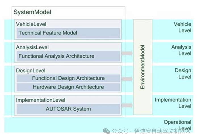 Figure 1. EAST-ADL Abstraction Layers and Orthogonal Environment Model [2]
Components communicate through specialized FunctionPorts. FunctionFlowPorts, inspired by SysML FlowPorts [17], are used for data flow-based communication. Additionally, for client-server interactions, components can interact through FunctionClientServerPorts. FunctionPowerPorts represent physical interactions between the environment and sensing or driving functionalities. FunctionPorts are typed by EADataTypes, which represent data types in EAST-ADL, such as integers specified within a range as EAInteger.Hardware components communicate through specialized HardwarePins. CommunicationHardwarePins represent hardware connection points of communication buses. PowerHardwarePin is used for modeling power. IOHardwarePins represent electrical connection points for digital or analog I/O.At the most abstract level, the vehicle feature layer only models the features of the vehicle, thereby allowing for the integration of product variations. All lower-level variations can be modeled through VariationPoints. Features can also be grouped and implemented by FunctionTypes. Different dependencies between features can be modeled as VariabilityDependencyKind. The focus at the analysis level is to model the system in a way suitable for analysis. The architectural model at this level is referred to as the functional analysis architecture. Components can be interconnected through analysis function types and functional device definitions (the latter representing actuators and sensors at the analysis level). Analysis functional prototypes represent instances of both. Software components are interconnected through functional connectors. At the design architecture level, software and hardware are represented in different models, namely functional design architecture and hardware design architecture. Software components are represented by design function types or local device managers (the latter representing software interfaces for sensors and actuators). Hardware components are modeled as nodes (ECUs), sensors, actuators, and logical buses. They are interconnected with hardware connectors. Logical buses represent the allocation targets of functional connectors, i.e., data exchanged in the functional design architecture. Nodes are allocation targets for design function types and local device managers. HardwareComponentPrototypes are properties defined using the aforementioned hardware types to represent instances.During the transition from design level to implementation level, a mapping to the AUTOSAR meta-model is anticipated. Consequently, modeling artifacts at this level comply with the AUTOSAR specification in version 3 [3]. The operational level refers to systems that have been deployed and are running, hence are not modeled. Behavior is not explicitly considered in EAST-ADL. It can be modeled externally (e.g., in domain-specific tools such as Matlab or platform-specific programming languages like C/C++) or internally using UML behavioral modeling (e.g., activity diagrams or state diagrams). As we have introduced EAST-ADL and its abstraction layers, the next section will outline the language and methods for abstracting different levels of SystemC. 4 SystemC – Transaction Level ModelingSystemC is a standardized system modeling and simulation language that supports hardware/software co-design and co-simulation. It is standardized and promoted by the Open SystemC Initiative (OSCI) [18] and has been approved by the IEEE Standards Association as IEEE 1666-2005 [4]. Based on the widely used programming language C++, SystemC provides artifacts for simulating concurrent processes and an event-driven simulation kernel. Although SystemC has semantic similarities to hardware description languages (such as VHDL and Verilog), it can be used to model entire systems using pure C++. SystemC models typically consist of several modules (sc modules) that can be organized hierarchically. Computation in SystemC is modeled by so-called processes, which are contained within modules. Processes are inherently concurrent. Communication from inside the module to the outside (mainly to other modules) is achieved through ports (sc ports). These ports are connected to channels (sc channels) via SystemC interfaces (sc interfaces). This allows for modeling complex communication structures (e.g., FIFO or network buses) in SystemC.Using SystemC, new models can easily connect to existing hardware or functional models – whether using platform-specific programming languages (like C/C++) or domain-specific modeling tools (like Matlab/Simulink in the automotive domain). Additionally, any existing C or C++ libraries can be included in one’s system model. Therefore, in the automotive domain, vendors can exchange pre-compiled hardware or software modules with other vendors or automotive manufacturers without disclosing their intellectual property.To effectively integrate hardware/software co-simulation during the development of networked embedded systems, models need to be refined gradually. This can be achieved by using SystemC, as it implements a top-down design process based on Transaction Level Modeling (TLM) [5]. TLM is a method for modeling digital systems that separates the communication details between computational components from the details of the computational components themselves. The details of communication or computation can be hidden in the early stages of design and added later. Therefore, communication mechanisms such as interconnect buses are modeled as sc channels, which can be accessed by sc modules using SystemC interface classes. Transaction requests are made by calling the interface functions of these channels. The low-level details of the communication process are encapsulated by sc interfaces. This separation allows for the evaluation of different interconnect systems without having to re-implement the computational model interacting with any bus, as the computational model interacts with the communication model through a common interface. The OSCI TLM working group has defined different levels of abstraction for TLM [19]. The most abstract level is represented as Communication Processes (CP). At this level, the behavior of the system is partitioned into parallel processes that exchange complex high-level data structures through point-to-point connections. Communication Processes with Timing (CPT) are the same as CP but introduce timing annotations. The next more detailed level, Programmer View (PV), is more architecture-specific. Bus models are instantiated as transport mechanisms between model components and some communication infrastructure arbitration is applied. Programmer View with Timing (PVT) is functionally the same as PV but annotates timing information more accurately than CPT. At the level called Cycle Callable (CC), the computational model is clocked, and all timing annotations are precise to the level of a single clock cycle. The communication model fully conforms to the protocol.After introducing the abstract levels of SystemC TLM, we will present the method of mapping the architectural descriptions of EAST-ADL to SystemC TLM in the next section.5 Simulation Validation Based on Architectural ModelsArchitectural models capture information on system development and allow for simulation-based validation. As described in Section 3, EAST-ADL supports modeling systems at different abstraction layers. With TLM, different levels for abstract modeling of systems have been introduced in SystemC (see previous Section 4). This combination of ADL with SystemC allows for iterative design through hardware/software co-simulation, providing early feedback on the model. To combine the advantages of ADL and simulation, the abstraction levels must be coordinated. Therefore, we will map the abstraction levels of EAST-ADL to SystemC TLM levels below, as shown in Figure 2.
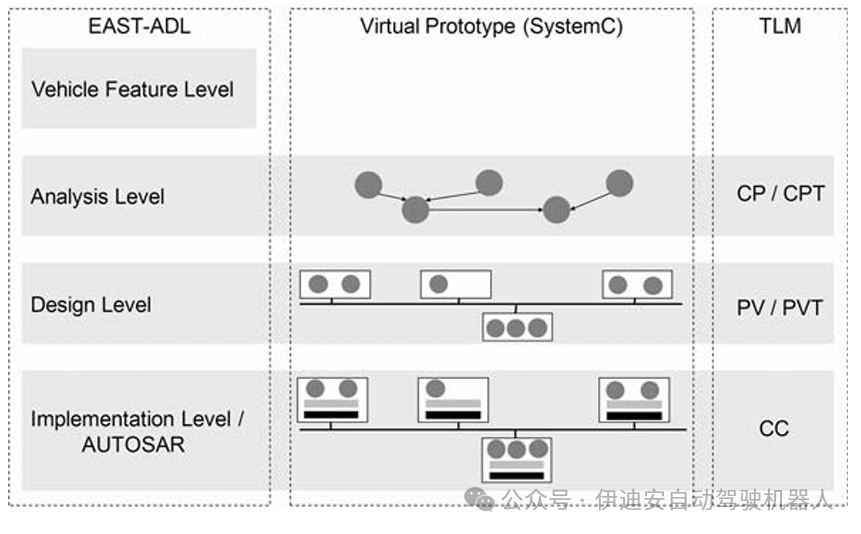 Figure 2 EAST-ADL Abstraction Layers Compared to SystemC TLM Layers
The most abstract functional layers in EAST-ADL and TLM are the analysis layer and CP. Since the vehicle layer contains only functionalities, it is not considered in the mapping of system behavior simulation. The TLM layer Communication Process (CP) represents parallel processes communicating through point-to-point connections. At the analysis layer, the interdependencies between modeling functionalities and their externally visible behaviors are described. The functions at the analysis layer represent abstract communication components. Thus, they can be transformed into parallel communication processes, and the analysis layer can be mapped to CP. The specific transformation of EAST-ADL components at this level is shown in the next section.Since CPT adds timing annotations to CP, it corresponds to the analysis layer considering time in the model. The next more detailed level is the design layer of EAST-ADL and TLM PV. Besides CP, the Programmer View (PV) also incorporates bus architecture and communication infrastructure arbitration. Additionally, the design level introduces hardware models and bus infrastructure in EAST-ADL and refines more abstract layers. Thus, the design level of EAST-ADL and its modeling software and hardware distributed across multiple ECUs can be mapped to PV in SystemC. Software functionalities (DesignFunctionTypes) represent processes, and hardware with interconnect buses can be modeled as hardware architecture and corresponding communication infrastructure. Since the time-annotated Programmer View (PVT) contains more precise timing information than the CPT level, it aligns with the model of the design level of EAST-ADL with timing. The most detailed functional abstraction layer in EAST-ADL is the implementation level. It is represented by the AUTOSAR model, containing the most detailed and accurate system information. Since this level is platform-specific, representing a specific implementation and providing the details required for cycle-accurate simulation, it can be transformed into the TLM Cycle Callable level (CC). The latter has cycle accuracy relative to a single clock cycle, making it very suitable for simulating time-accurate AUTOSAR models. As shown in Figure 2, the aligned abstraction levels include specific artifacts of the modeling language that need to be transformed for mapping. These are the focus of the next subsection.5.1 Mapping EAST-ADL Artifacts to SystemC TLMIn the previous section, we pointed out the general commonalities between the different abstraction levels of EAST-ADL and SystemC. To integrate validation in SystemC, individual artifacts of EAST-ADL must be mapped to SystemC language elements. Below, we will discuss the mapping of structural parts between the two functional layers of EAST-ADL (analysis layer and design layer). Since the implementation layer is realized through the AUTOSAR model, the mapping is independent of EAST-ADL and instead relates to the AUTOSAR meta-model. Therefore, SystemC TLM simulations can be implemented using an AUTOSAR software component-based approach, as described in [11]. Through this transformation, special emphasis must be placed on semantic mapping and the preservation of defined artifacts. The structure of the models is preserved in the transformation. Therefore, model artifacts can be traced back to SystemC code-level artifacts, but the downside is that the code is not optimized. This also allows for feedback from the simulation to the corresponding model elements.The following mapping focuses on the structural parts of the language, as behavior is not explicitly modeled in EAST-ADL (see Section 3). In the latest version of EAST-ADL, time definitions have been integrated as non-functional properties. Since this involves non-functional properties of time, it does not define functional behavior. The integration of EAST-ADL’s time semantics (Timing Augmented Description Language [20]) is currently underway as future work. The architectural model only contains references to externally specified behaviors (e.g., UML behaviors or Matlab/Simulink models). Therefore, behaviors can be directly mapped to SystemC. To achieve the mapping of behaviors, off-the-shelf C/C++ code generators can be used to generate referenced behaviors, such as TargetLink or UML state diagram generators. The generated platform code can be integrated as the behavior of SystemC modules (sc modules). The orthogonal environment model can be represented by a single sc module that includes environmental behaviors as sub-modules, such as code generated from Matlab/Simulink models. ClampConnectors are specific elements for interfacing the environment components with the horizontal functional analysis architecture and functional design architecture. This connection can be realized through sc channels and sc interfaces in SystemC.In the previous section, we explained the general relationship between the analysis level of EAST-ADL and the CP level of TLM. To specifically map these levels, rules must be defined for transforming EAST-ADL artifacts into SystemC elements. As shown in Figure 3, EAST-ADL components can typically be represented by sc modules. EAST-ADL ports and connectors can be transformed into sc ports, sc channels, and sc interfaces.
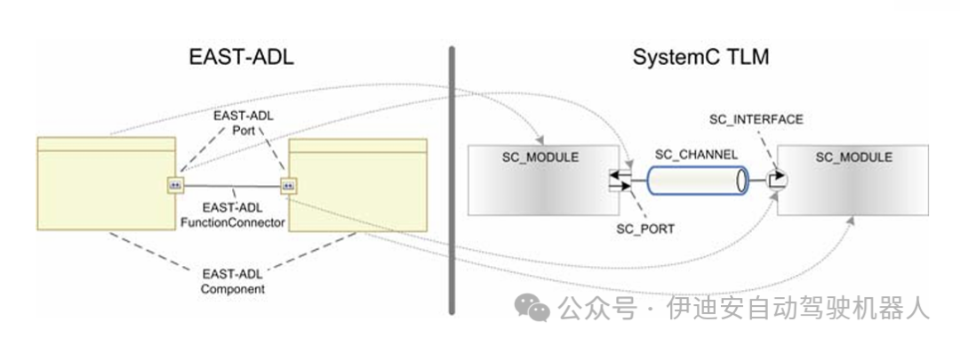 Figure 3 Mapping EAST-ADL Artifacts to SystemC Elements
At the analysis level, sensors and actuators are represented by FunctionalDevices. AnalysisFunctionTypes are used to model functionalities. These components can be directly transformed into sc modules. FunctionFlowPorts are ports for data flow between AnalysisFunctionTypes. FunctionClientServerPorts can be used for functional calls through defined interfaces. Ports are interconnected through FunctionConnectors. Ports and connectors at the CP level are transformed into simple sc signals or sc channels and sc interfaces.
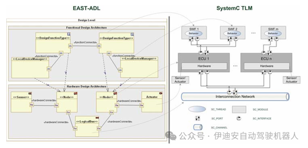 Figure 4. Mapping EAST-ADL Design Level to SystemC PV Simulation
At the design level, the simulation of software functionalities distributed across the hardware platform (ECU) is addressed. Therefore, we introduce a SystemC-based framework that allows for modeling automotive-specific elements in SystemC PV, such as ECUs or software functionalities. As shown in our PV approach, the system is simulated in PV, where software functionalities are arranged on ECUs communicating through interconnect buses. Individual components in SystemC are specialized sc modules. For instance, DesignFunctionType is mapped to the software functionality (SWF) defined in the framework, which originates from sc modules. Figure 4 provides an overview of the general mapping of EAST-ADL elements at the design level to SystemC. The design level consists of software and hardware models. DesignFunctionType represents software functionality. Software interacting with hardware sensors and actuators is modeled as LocalDeviceManager. Hardware components at this level are sensors, actuators, and LocalBus. These components can be transformed into PV-level sc modules, as described above. HardwarePorts and HardwareConnectors are transformed to sc channels and sc interfaces. Table 1 provides an excerpt of the main EAST-ADL elements and their corresponding SystemC elements. In the next section, these transformation rules are applied to an automotive case study, emphasizing their applicability for iterative validation based on architectural models during the development process.
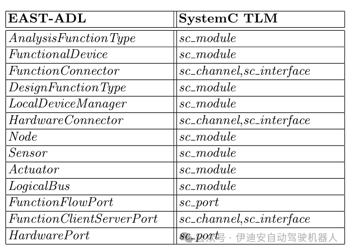 Table 1. Overview of Mapping Core EAST-ADL Elements to SystemC TLM Elements
6 Case StudyIn the case study of the transformation from EAST-ADL to SystemC described above, the application of architectural models in simulation validation was evaluated. Thus, the focus of this work is more on structural mapping and simulation generation than on validation or analysis itself.The transformation of EAST-ADL models to executable SystemC models presented earlier has been implemented in a prototype toolchain. For evaluation purposes, an automotive case study [21] has been modeled in EAST-ADL and transformed into SystemC simulation. The use case falls within the so-called body domain of the vehicle and includes four functionalities: external lighting, direction indication, central door locking, and keyless entry.
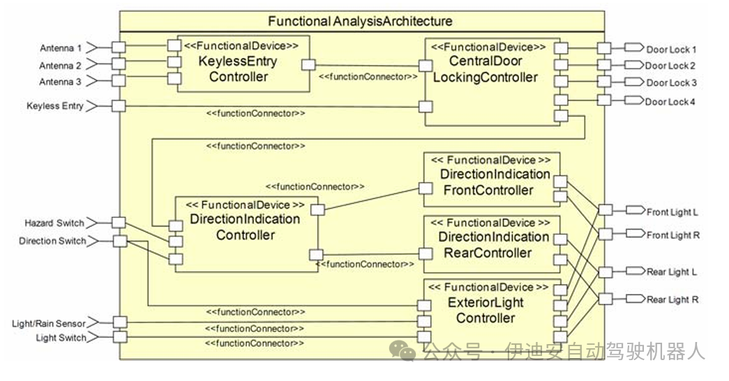 Figure 5. Composite Diagram of Analysis-Level Use Case
The external lighting functionality allows for controlling the vehicle’s front and rear lights. Lights can be manually or automatically turned on/off based on darkness or rain detected by rain/light sensors. These inputs are interpreted by the external lighting control functionality that controls the lighting units (front and rear lights). For direction indication, a turn signal switch can be used to signal the turning direction. Using the hazard signal light switch, a signal can be sent to other road users indicating a hazardous driving situation. Therefore, the direction indication master controller communicates the designated state of the direction indicators to the front and rear direction indication controllers. These indicators will turn on or off the direction indicators of the front and rear lights units. The central door locking allows for locking and unlocking all doors simultaneously using a key in the lock or via radio transmission. The radio receiver sends information to the central door locking controller. This functionality will flash the direction indicators to provide feedback to the driver and control the locks of the four doors of the vehicle.Another functionality for unlocking/locking the vehicle is keyless entry. The driver can keep the key in their pocket close to the vehicle, and the doors will automatically unlock. The doors can be locked by simply pressing a button on the door handle. The antenna component detects the key nearby and notifies the central door locking functionality, which then unlocks the doors. Regarding interaction with external light (providing feedback through direction indicators), there is no distinction whether the doors are unlocked in the standard way or through keyless entry. Below, the implementations of these functionalities at the analysis level and design level in EAST-ADL, as well as their corresponding SystemC implementations, will be described. At the analysis level, this use case is modeled in EAST-ADL with functional devices KeylessEntryController, CentralDoorLockingController, DirectionIndicationMasterController, DirectionIndicationFrontController, DirectionIndicationRearController, and ExteriorLightController, as shown in Figure 5. The behaviors of these functionalities are described as opaque behaviors of the components (C++ source code). Additionally, behaviors can be modeled using direct UML state diagrams that provide UML-based behavioral specifications. Communication is designed as data flow represented by FunctionFlowPorts and FunctionConnectors. The SystemC simulation generated from this level includes modules interconnected with each of the aforementioned functional devices. They implement the respective behaviors of these modeling components in the threads of the module. Through this transformation, simulation of the analysis level of EAST-ADL based on the use case has been achieved. Therefore, simulation-based analysis can be used to validate the interactions of abstract modeling functionalities.
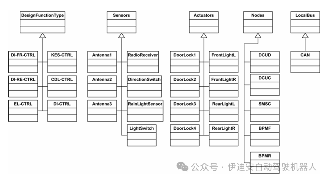 Figure 6. EAST-ADL Elements of Use Case at Design Level
At the design level, the use case is modeled in the Functional Design Architecture (FDA), representing the software part, and in the Hardware Design Architecture (HDA), representing the hardware part implementing the use case. The FDA includes design function types of the use case software functionalities and local device managers representing software access to the modeled sensors and actuators. The latter is designed in HDA along with the hardware platform (nodes) and interconnect local buses. Components in the FDA are interconnected with functional connectors, while components in the HDA are interconnected with hardware connectors. Figure 6 provides an overview of the elements modeled for the use case at the design level. Additionally, each depicted sensor and actuator in the functional design architecture has a local device manager, although not explicitly shown in this figure.
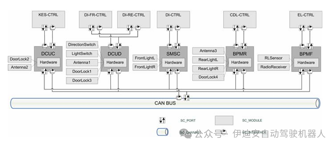 Figure 7 Overview of Generated SystemC PVT Use Case
Figure 7 shows the generated SystemC implementation of the design-level use case. It includes the use of automotive-specific module frameworks. For example, ECUs and software functionalities can be implemented as specific sc modules from a library (see Section 5.1). As shown in Figure 7, EAST-ADL design-level components are generated as sc modules representing software functionalities. These modules are contained within another SystemC module, which implements a hardware platform with additional sensors and actuators in the form of sc modules. These hardware platforms are interconnected through defined LocalBus modules. SystemC interfaces and channels realize the specific interconnections of the modules. For instance, a specialized sc interface (EcuSw If) implements the communication between the software functionalities and the ECU module.The introduced transformations have been implemented in a prototype toolchain, which has been integrated as a plugin into the Eclipse environment. This allows it to be easily used with EAST-ADL models based on UML in Eclipse (for example, using the Papyrus UML modeling tool that supports EAST-ADL). The transformations themselves are implemented as templates in the Xpand model-to-text transformation language. They use the EAST-ADL model as input and generate specific SystemC files based on the previously introduced language mappings. Currently, simulations can be generated from either the analysis level or the design level. Simple checks allow for verifying the consistency of the simulations. Since generating incomplete models in the early design phase should be possible, the strictness of the checks is limited to the degree necessary for generating correct SystemC simulations. This supports iterative simulation of ADL models during the design process. For design-level simulations, we used a self-developed framework called DynaSim (see Section 5.1), which allows for modeling automotive onboard networks in SysTemC. The generated files reference SystemC models in the DynaSim library (e.g., ECU or software functionalities). This allows for simulations considering the automotive-specific system environment. Future work will focus on automated feedback to the models and the integration and analysis of timing definition semantics.7 ConclusionArchitecture Description Languages capture design information within architectural models. Simulating these models during development allows for early validation. In this work, we briefly introduced the automotive-specific EAST ADL and the system modeling language SystemC. We demonstrated that simulations can be automatically generated from EAST-ADL by transforming to SystemC. Thus, the abstraction layers of EAST-ADL were compared and mapped to the corresponding layers of SystemC TLM. Furthermore, the transformation rules between EAST-ADL modeling artifacts and specific target elements in SystemC were presented. A case study in the automotive domain evaluated the method, focusing on generating simulations from EAST-ADL models at two different abstraction layers. To this end, we constructed a prototype toolchain that allows for the automatic generation of SystemC simulations from EAST-ADL models. In this way, we showed that our method enables iterative simulation-based validation of automotive functionalities across different abstraction layers. In future work, we plan to improve this method by focusing on the preservation of simulation and non-functional requirements (e.g., timing) as well as integrating externally defined models. Additionally, more detailed automotive-specific SystemC models will be integrated into the simulations for more accurate analyses. We will particularly emphasize the design of adaptive embedded systems and simulation-based validation.