The advancement of technology in various fields has led to an increasing demand for industrial equipment. The industrial fieldbus used in traditional automation control systems is limited by outdated protocol technologies and hardware specifications, making it increasingly difficult to meet the growing demands for data transmission speed and real-time performance. EtherCAT, as a high-performance, real-time industrial Ethernet communication protocol, is fully capable of meeting the requirements for fast response and high precision in data transmission between automation, control, and industrial devices. Digital Signal Processors (DSPs) are specialized microprocessors designed for digital signal processing. They feature high-speed computation, low power consumption, and strong data processing capabilities, making them particularly suitable for motion control systems that require real-time processing. Even in complex control scenarios, the sampling period can be minimized, and the control effect can closely resemble that of a continuous system. Combining the advantages of DSPs and ESC chips will be an excellent choice for high-performance CNC systems.
01Introduction to the FCE1100_FCP32C335 Function Board
FCE1100_FCP32C335 Function Board serves as a development and evaluation platform for EtherCAT communication technology, providing experienced customers with an assessment of the complete domestic EtherCAT solution. It also helps novice customers quickly understand the characteristics of EtherCAT communication and the use of DSPs, laying the foundation for subsequent development of their own solutions.
FCP32C335——A high-performance DSP chip comparable to TI TMS320F28335, empowering industrial control and smart devices!

FCE1100: What are the absolute advantages of the domestic EtherCAT slave chip compared to Beckhoff ET1100?
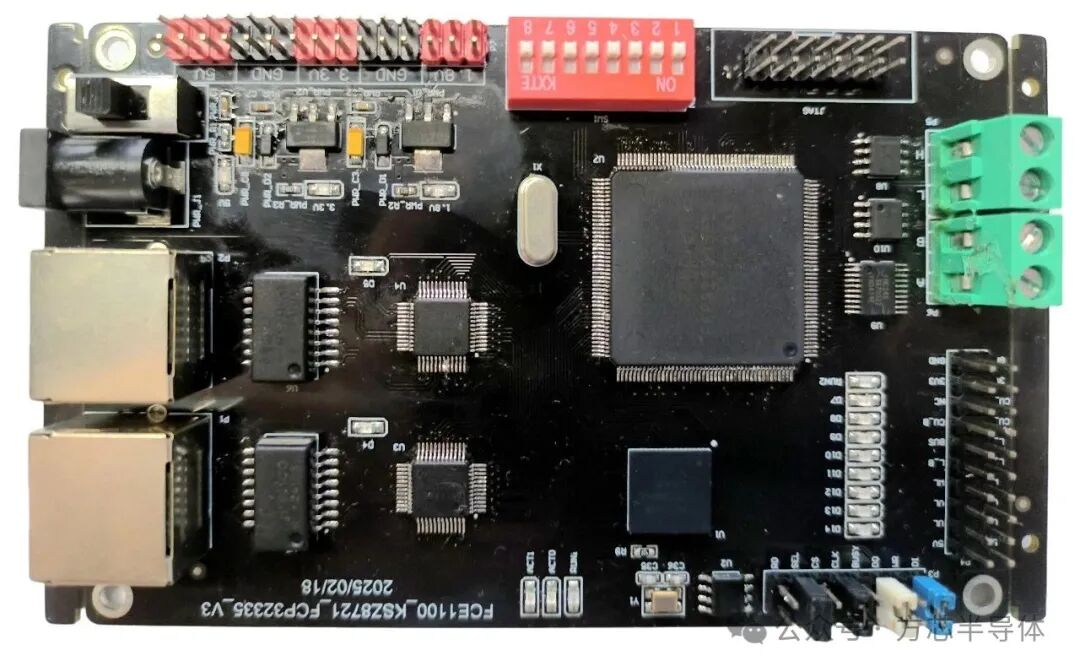
FCE1100_FCP32C335 Function Board is an industrial Ethernet development board based on the domestic EtherCAT slave control chip FCE1100 and the domestic DSP chip FCP32C335. The FCE1100 is responsible for processing and forwarding EtherCAT data frames, while the FCP32C335 runs the EtherCAT slave protocol stack code to implement basic I/O functions.
The development board is equipped with two RJ45 connectors connecting two KSZ8721PHY chips. Additionally, an external EEPROM chip is mounted on the evaluation board to store device description information and initial configuration of the chip. This EEPROM can be programmed with different XML files via EtherCAT master or SSC.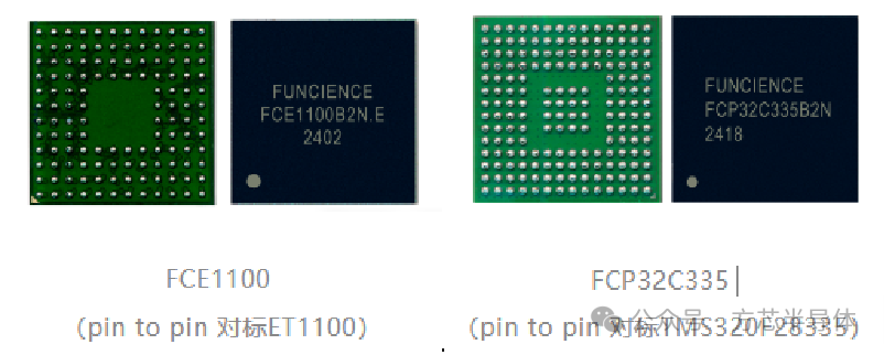 The power supply section of the development board uses an AMS1117-3V3 external LDO chip, responsible for powering the FCE1100 and FCP32C335 I/O. An AMS1117-1V8 external LDO chip is used to power the FCP32C335 core. The development board supports 5V DC power supply and can be powered via pin headers or DC connectors, allowing customers to choose between different power supply voltages.
High precision, low power consumption! Introduction to the domestic DSP FCP32C335 chip and development board
01Features of the FCE1100_FCP32C335 Function Board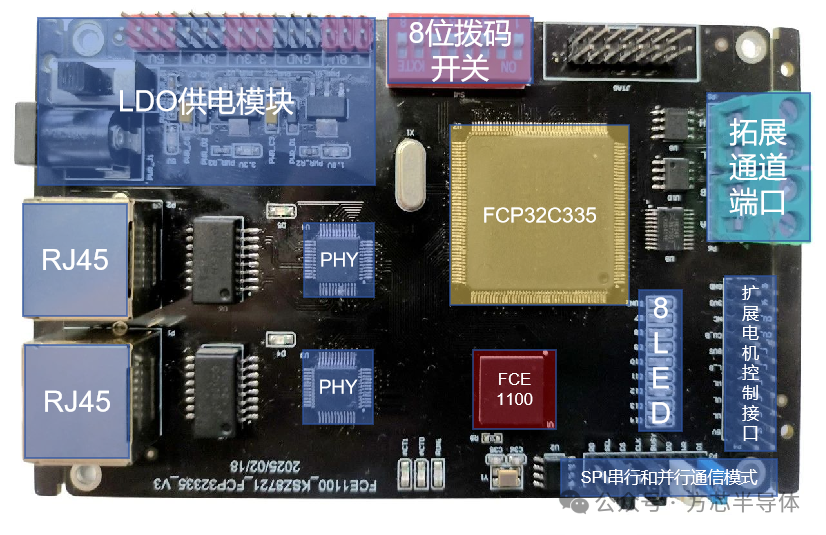
FCE1100_FCP32C335 Function Board Structure Diagram
-
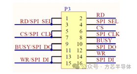
The communication design between FCE1100 and FCP32C335 is split into two, supporting configurable SPI serial communication and parallel communication modes, with jumpers to switch between the two communication methods on the hardware connection.The schematic diagram is shown below:
-
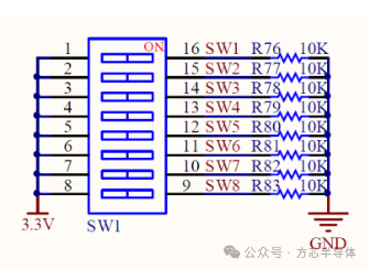
The development board integrates an 8-bit dip switch for testing the digital input function of the slave controller.The schematic diagram is shown below:
-
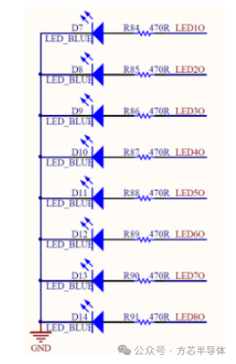
The development board is designed with 8 LEDs for testing the digital output function of the slave controller. The schematic diagram is shown below:
-
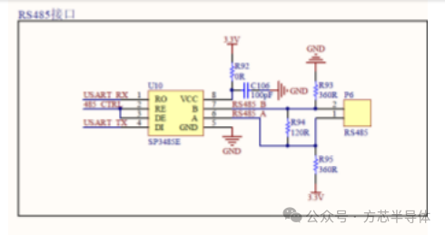
Expansion communication ports: RS485. In the design of the development board, the SCI communication interface of FCP32C335 is connected to an RS485 transceiver chip, which can be used for RS485 communication.The schematic diagram is shown below:
-
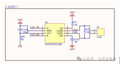
Expansion communication ports: CAN. The design of this development board connects the CAN communication interface of FCP32C335 to a CAN transceiver chip, which can be used for CAN communication.The schematic diagram is shown below:
-
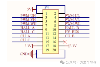
Expansion motor control interfaces. Several important motor control pins are brought out to the pin header on the development board, including 6 EPWM pins, 3 GPIO pins, and 4 ADC pins from FCP32C335. These can be connected to external motor driver boards to achieve motor driving functions.The schematic diagram is shown below:
The above solution board is available for free schematic and physical board testing from Fangxin. Please feel free to contact us.
Contact Us

Long press the QR code to add WeChat and contact us
 Product ConsultationEmail: [email protected]
Phone: (010) 62901860-681/689
Address: No. 1, Gao Lizhang Road, Building 2