PROFIBUS DP Basic Introduction
PROFIBUS DP is a classic fieldbus protocol introduced by Siemens many years ago, widely used in various industrial applications. With more domestic manufacturers participating in the production and manufacturing of PROFIBUS DP related devices, various designs for the physical connection of PROFIBUS DP have emerged. To facilitate everyone in designing the physical interfaces of products, we have organized knowledge related to the 9-pin D-sub connector.
PROFIBUS DP 9-pin D-sub connector
Interpretation of PROFIBUS DP Specifications
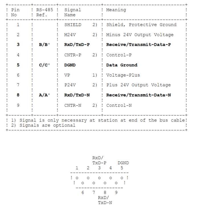
The PROFIBUS DP specification Part 2 Physical Layer Specification and Service Definition clearly defines the bus connector as follows:
For convenience, the key parts of the specification are interpreted as follows:
① Each device needs to connect to the bus via a DB9 connector, with the device using a female connector and the bus using a male connector;
② Required signals in DB9: 3- differential signal positive, 8- differential signal negative, 5- signal ground, 6- terminal voltage;
③ Optional signals in DB9: 1- shield ground, 2- 24V negative, 7- 24V positive, 4- direction control positive, 9- direction control negative;
Considerations for RS485 Differential Signals
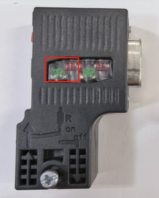
When engineers use the standard PROFIBUS DP interface, they can see the labels B and A representing the positive and negative of the RS485 differential line, respectively. Note: the labeling here may be opposite to that in the RS485 chip manual, which must be carefully considered during design.
Dealing with Interference in RS485 Differential Signals
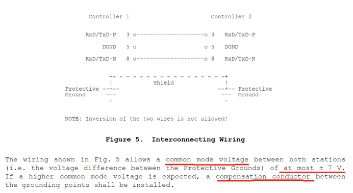
In industrial environments, differential signals are susceptible to interference (especially when signal cables exit control cabinets). This interference is mainly caused by common-mode voltage. If the common-mode voltage does not exceed +/-7V, the signal ground can remain unconnected. When higher common-mode voltages are present, connection should be considered.
RS485 Differential Signal Termination Matching
Interpretation is as follows:
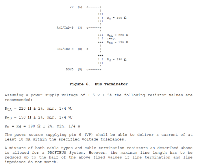
① The Rt resistor mainly serves to absorb reflected signals, while Ru and Rd are two compensation resistors used to force the differential voltage on the bus to remain in the “1” state during idle time;
② The Rt resistor needs to be matched according to the impedance of the bus cable;
③ The device needs to provide the required 5V, meeting voltage and current requirements;
Summary of Issues Encountered in Practical Applications
① The situation where the RS485 differential lines are reversed;
② The situation where the bus 5V power supply is not provided;
③ Direction control signal processing;
For issue 3, Jiyuan suggests that customers can lead out the isolated send enable signal based on their RS485 transceiver circuit, and connect it to pin 4 of the DB9 through a resistor of 100~300 ohms for current limiting. For applications with higher EMC requirements, it is not recommended to lead out this signal, or special handling of this signal is required.

010-85958895 / [email protected]12 Tianchen Building, No. 12 North Chaoyangmen Street, Chaoyang District, Beijing