Author | Tianrongxin
1. Overview
EtherCAT (Ethernet for Control Automation Technology) is a real-time industrial fieldbus communication protocol based on Ethernet, originally developed by Beckhoff Automation GmbH in Germany. It was introduced to the market in 2003, became an international standard in 2007, and became a national standard in China in 2014. The emergence of EtherCAT has set new standards for system real-time performance and topological flexibility.
EtherCAT features also include high-precision device synchronization, optional cable redundancy, and functional safety protocols (SIL3).
2. Principle
The EtherCAT technology breaks through the system limitations of other Ethernet solutions: with this technology, it is not necessary to receive Ethernet data, decode it, and then copy the process data to each device. EtherCAT is a real-time Ethernet technology composed of one master device and multiple slave devices. The master can be implemented using a standard network card, while the slaves use specific EtherCAT Slave Controllers (ESC) or FPGAs. The EtherCAT message (standard ISO/IEC 8802-3 Ethernet frame) is sent by the master device, passing through each slave device, which extracts or inserts data as the message passes. When the message reaches the last slave device in the segment, it is transmitted back in the reverse direction, finally returned to the master device by the first slave device, which collects the information.
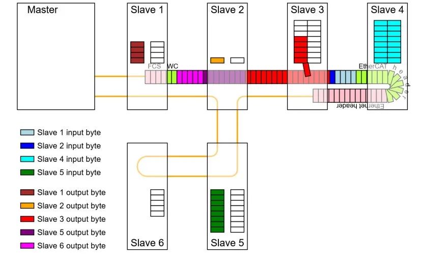
Figure 2.1 Insertion of Process Data into the Message
3. Topology
EtherCAT supports various topological structures such as bus, tree, or star. The bus structure, named after the fieldbus, or linear structure can also be used with Ethernet and is not limited by the number of cascading switches or hubs. The most effective way to connect the system is to combine linear, branch, or tree structures topologically. Since the required interfaces already exist in many devices such as I/O modules, no additional switches are needed, and Ethernet-based star topologies can also be used. The EtherCAT system can accommodate up to 65,535 devices, so the overall network scale is virtually unlimited.
Using different transmission cables can maximize the flexibility of wiring. Flexible and low-cost standard Ethernet patch cables can transmit signals via Ethernet mode (100baseTX) or through the E-bus. Optical fibers (PFO) can be used for special applications. Ethernet bandwidth (such as different optical and copper cables) can be used in conjunction with switches or media converters. The physical characteristics of Fast Ethernet allow distances between devices to reach 100 meters, while the E-bus can only guarantee a spacing of 10 meters. Fast Ethernet or E-bus can be selected according to distance requirements.
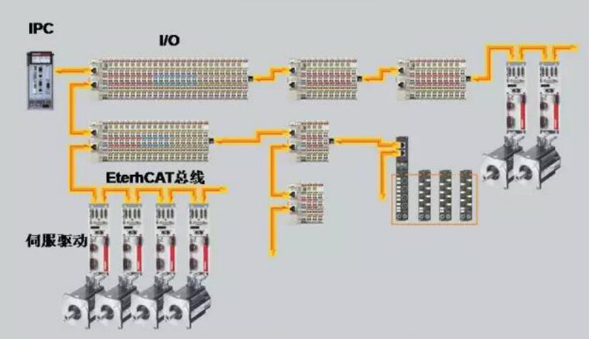
Figure 3.1 Flexible Topological Structure
4. Protocol Format Introduction
4.1 EtherCAT Ethernet
EtherCAT data can be transmitted using standard IEEE 802.3 Ethernet data frames, formatted as shown in Figure 4.1, consisting of an Ethernet header, EtherCAT frame, and FCS (Frame Check Sequence).

Figure 4.1
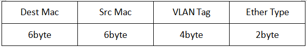
4.1.1 Ethernet Frame Header
Dest Mac and Src Mac represent the receiving MAC address and the sending MAC address, respectively. VLAN Tag is an optional field that can be omitted, with values of 0x81,0x00 and 2-byte Tag Control Information as specified by IEEE 802.1. The Ether Type value is 0x88A4, indicating the EtherCAT protocol.
4.1.2 EtherCAT Frame
The EtherCAT frame format is shown in Figure 4.2, divided into a header and data section.

Figure 4.2
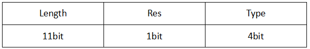
EtherCAT Header:
The Length field indicates the length of the EtherCAT data, Res is reserved, and the Type value varies depending on the subsequent EtherCAT data format, which can take the following values:
0x0001: EtherCAT DLPDU
0x0004: Network variable
0x0005: Mailbox
EtherCAT Data (mainly introducing EtherCAT DLPDU):
EtherCAT data consists of multiple sub-messages as shown in Figure 4.3, each sub-message consists of a sub-message header, data, and WKC.

Figure 4.3
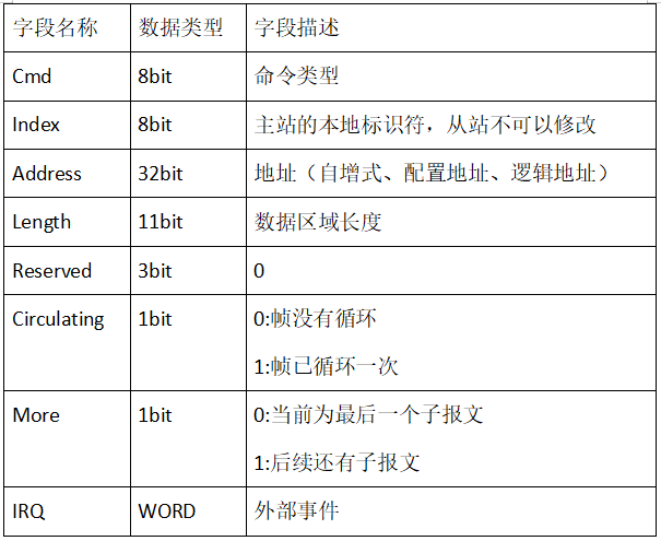
Sub-message Header:
Data:
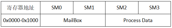
The type of data is determined by the Cmd and Address fields. The first 16 bits of Address represent the slave address, and the last 16 bits represent the register address. When Cmd is of logical addressing type, the entire 32 bits of Address represent the logical address. If the register address is greater than 0x1000, consider whether it is mailbox data; the address for mailbox data in the slave is SM0-SM1, with SM0 starting at 0x1000, and SM2-SM3 belonging to FMMU (Fieldbus Memory Management Unit), which can only be accessed logically.
WKC:
WKC (Working Counter) is initially set to 0 by the master. When the sub-message passes through the slave, WKC is incremented, with the increment value varying based on Cmd. When the data frame returns to the master, the master device checks the WKC value to determine whether the message was processed correctly.
4.1.3 FCS
The receiver can use the FCS value to determine whether the data is complete.
4.2 EtherCAT UDP
In 4.1, the message format for EtherCAT transmitted using Ethernet frames was introduced. The EtherCAT protocol can also be transmitted as UDP/IP datagrams, as shown in Figure 4.4. The main difference in message format is the addition of the IP header and UDP header; the EtherCAT UDP protocol is suitable for scenarios where strict real-time requirements are not necessary.

Figure 4.4
4.3 Message Example
The Ethernet header containing the EtherCAT frame is shown in Figure 4.5:

The EtherCAT frame header is shown in Figure 4.6:
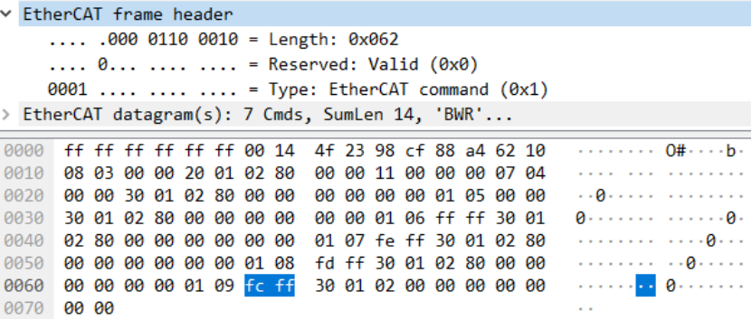
Figure 4.6
One of the sub-messages in the EtherCAT frame data is shown in Figure 4.7:
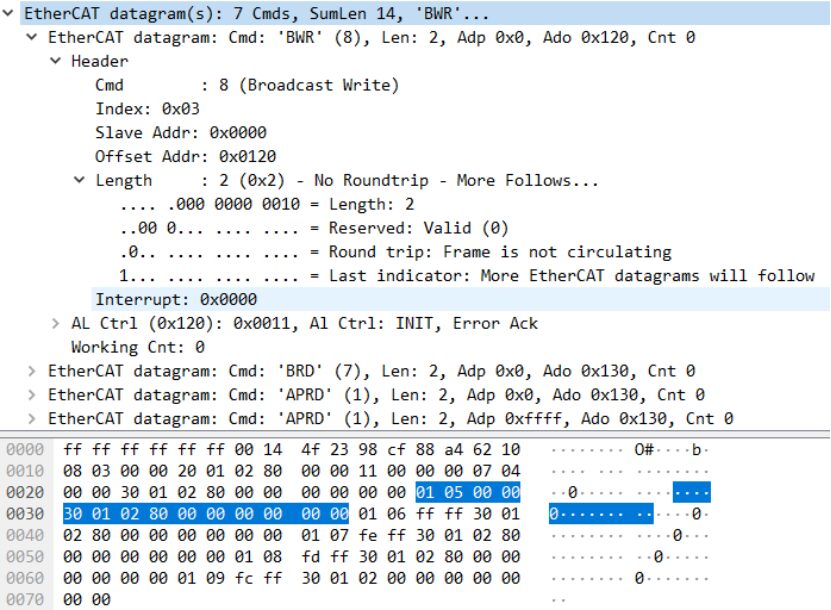
Figure 4.7
5. Addressing Methods and Command Types
In the EtherCAT sub-message, the Address field is used to address EtherCAT devices, with addressing methods including position addressing, node addressing, and logical addressing.
5.1 Position Addressing
Position addressing is implemented based on the physical location of the slave. In the sub-message header, the first 16 bits of the Address field store the address value. Each time the message passes a slave device, the address value increments by 1. When the slave receives a message with an address value of 0, it indicates that this is the message the slave needs to receive.
5.2 Node Addressing
Node addressing is done by configuring the node address during the data link layer startup phase by the master. This ensures that even if the topology of the segment changes or devices are added/removed, the slave devices can still be addressed using the same address configuration.
5.3 Logical Addressing
First, it is necessary to understand the FMMU (Fieldbus Memory Management Unit), which exists in the slave chip ESC and is mainly responsible for establishing the mapping relationship between the slave physical address and the master logical address. Logical addressing uses the entire space of the Address field in the sub-message header to represent a 4GB logical address space. When the slave receives the message, it checks whether the address in the message matches the address in the FMMU. If they match, it performs read/write operations based on the specific command.
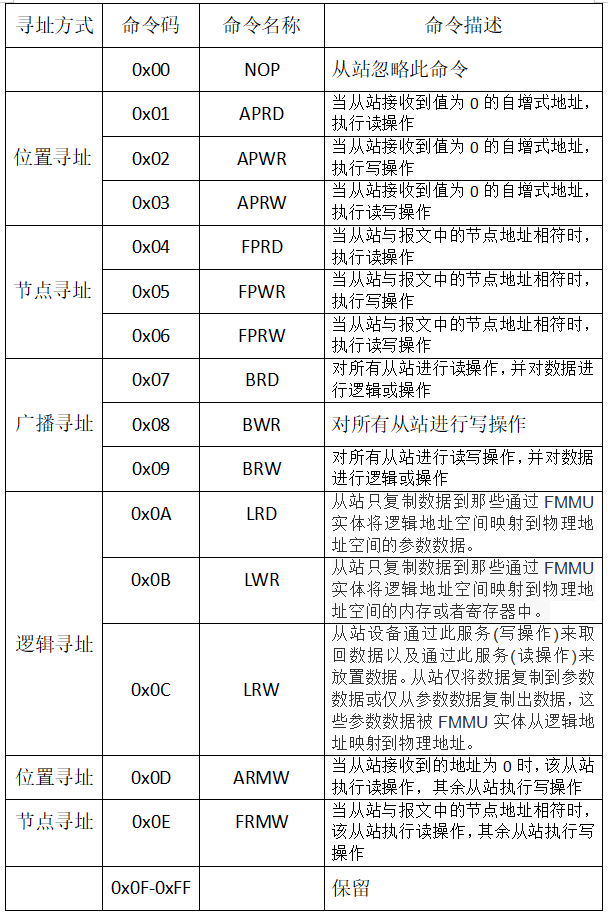
5.4 Command Types
EtherCAT can classify command types based on different addressing methods.
6. Conclusion
EtherCAT has various mechanisms to support communication from master to slave, slave to slave, and master to master. It implements safety features using technically feasible and cost-effective methods, allowing Ethernet technology to extend down to the I/O level. EtherCAT is superior in functionality, fully compatible with Ethernet, can embed Internet technology into simple devices, and maximizes the enormous bandwidth provided by Ethernet, making it a real-time performance superior and cost-effective network technology.