The basic working method of a PLC is to sequentially execute the user program, executing one instruction per clock cycle. There are generally two types of execution for the user program: cyclic scanning and timed scanning. The scanning process is divided into three stages: input sampling stage, program execution stage, and output refresh stage, as shown in Figure 1.
(1) Input Sampling Stage. In the input sampling stage, the PLC sequentially reads the status of all input terminals in a scanning manner and stores them in the input register, then moves on to the program execution stage.
(2) Program Execution Stage. In the program execution stage, the PLC sequentially scans each instruction. It first reads the status of all input terminals from the input register.
Figure: PLC Program Execution Process
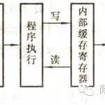
(3) Output Refresh Stage. After all instructions have been executed, the status of all outputs in the output register is sent to the output circuit, becoming the actual output of the PLC.
Completing the above three stages is referred to as one scanning cycle of the PLC.
If categorized by application type, the applications of programmable controllers mainly include the following three types:
(1) Switch Logic and Sequential Control: This is the most basic control function of the PLC, widely used in industrial settings, and can replace relay control systems. Switch logic control can be used not only for single devices but also for production lines.
(2) Process Control: The PLC can control continuously changing analog quantities such as temperature, flow, and pressure through analog I/O modules. Medium and large PLCs generally have PID closed-loop control functions and are widely used in industries such as electric power, chemical engineering, machinery, and metallurgy.
(3) Motion Control: The PLC can be applied to control linear or circular motion, such as in CNC machine tools, robots, metal processing, and elevator control.
|
The composition of the PLC in a robotic control system is as follows: 1. Input Unit: The input unit consists of 8 buttons, 8 switches, and 16 connectors, which connect to the 16 input points of the PLC. Changing the on/off state of these switches or buttons can provide the required switch quantities for the main machine. The 16 connectors can be used to externally connect other DC or switch quantity input signals. 2. Output Unit: The output unit consists of 24 diodes and 24 connectors, which connect to the 24 output points of the PLC. Whether the light-emitting diodes are lit indicates the status of the output points, allowing users to obtain output information from the main machine. The 24 output connectors can be used to externally connect other devices that need to be controlled. The output unit has 4 ground terminals, which lead to the panel, of which only C4 is grounded with the 3V power supply. 3. Power Supply Unit: The left side of the PLC host has an external 220V/AV power socket, serving as the working power supply for the PLC. It has a built-in transformer that outputs a 3V power supply for the diodes. Additionally, the 24VDC and 24GND of the PLC have been led out to the panel for the working power supply of external input devices (such as sensors). |
|
Main steps and content to follow when designing a PLC control system: (1) Process Analysis Deeply understand the process, working characteristics, and control requirements of the control object, and divide the various stages of control, summarizing the characteristics of each stage and the transition conditions between stages, drawing control flow charts or functional flow charts. (2) Choose the appropriate type of PLC When selecting a PLC model, the following points are mainly considered: 1. Selection of functions. For small PLCs, mainly consider I/O expansion modules, A/D and D/A modules, and instruction functions (such as interrupts, PID, etc.). 2. Determining the number of I/O points. Count the number of I/O points for the switch quantities and analog quantities in the controlled system, and consider future expansions (generally adding 10% to 20% as a reserve), thus selecting the I/O points and output specifications of the PLC. 3. Estimating memory. The memory capacity required for the user program is mainly related to the number of I/O points, control requirements, and the length of the program structure. Generally, it can be estimated using the following formula: storage capacity = switch input point number × 10 + switch output point number × 8 + analog channel number × 100 + timer/counter quantity × 2 + number of communication interfaces × 300 + reserve. (3) Allocate I/O points. Allocate the input/output points of the PLC, write an input/output allocation table or draw a wiring diagram for the input/output terminals, and then proceed with PLC program design while simultaneously designing the control cabinet or operation panel and on-site construction. (4) Program Design. For more complex control systems, based on production process requirements, draw control flow charts or functional flow charts, then design ladder diagrams, and compile statement list programs based on the ladder diagrams, simulating and modifying the program until it meets control requirements. (5) Design of control cabinet or operation panel and on-site construction. Design the electrical layout and installation wiring diagrams of the control cabinet and operation panel; design the electrical interlocking diagrams of each part of the control system; perform on-site wiring according to the drawings and check. (6) Overall debugging of the application system. If the control system consists of several parts, partial debugging should be done first, followed by overall debugging; if the control program has many steps, partial debugging can be done first, then connect them for total debugging. (7) Prepare technical documents. Technical documents should include: external wiring diagrams and other electrical drawings of the programmable controller, electrical layout diagrams, detailed lists of electrical components, sequential functional diagrams, ladder diagrams with annotations, and explanations. |
|
Usage and Status Numbering of PLC Status Relays Status relays are important internal components for controlling systems in the PLC stepwise control system. They are used in combination with the stepwise control instruction STL, utilizing state transition diagrams to compile efficient and understandable programs.Status relays are generally divided into four categories, with the following numbering and points: Initial State: S0∽S9 (10 points); Reset: S10∽S19 (10 points); General: S20∽S499 (480 points); Hold: S500∽S899 (400 points); Alarm: S900∽S999 (100 points); |
Images are sourced from the internet. If there is any infringement, please contact us for removal!


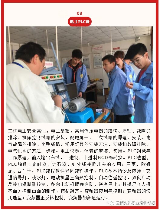
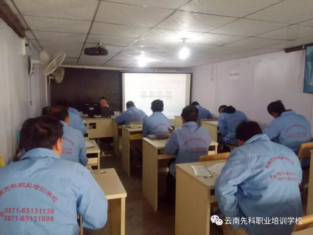
Electrical PLC Class @ Theoretical Course Explanation
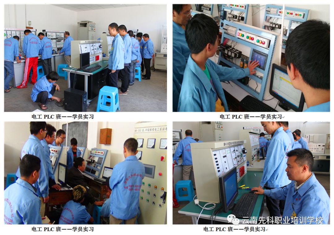
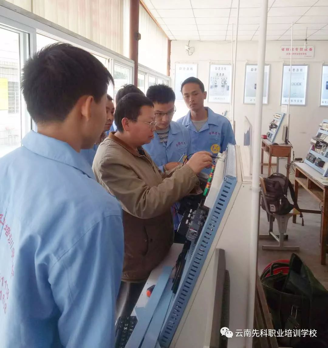
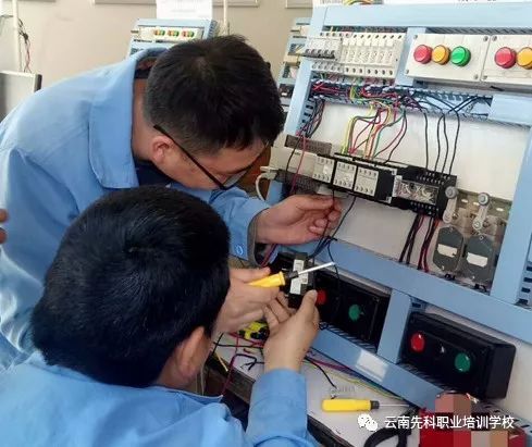
Electrical PLC Class @ Student Practice
Year-round enrollment, classes start every month; cyclic teaching, learn anytime, unified accommodation; job placement assistance!
1. Registration Methods:
Registration can be done at any time, on-site registration, WeChat registration, and QQ registration are all acceptable.2. Registration Conditions:
(Zero-Basis Training Class)1. No age, gender, or regional restrictions;2. No educational restrictions;3. Must meet corresponding physical conditions.3. Registration Hotline:
Contact Number: 0871—65131138Address: 485 Tanhua Road, Kunming (next to the back gate of Tanhua Temple Park)Website:www.ynxk.com.cn