Did you know that any complex engineering application consists of several basic programming steps? Therefore, we must master the basic programming steps and some typical basic control designs.
Today’s article introduces the most basic controls of the PLC control system, including initialization control, fault control, output prohibition control upon power recovery, and multi-condition selection control.

Generally, in PLC control, the device needs to be initialized before entering the normal control phase. These initialization tasks only run at the beginning of the PLC power-up phase, and once the PLC is running normally, these initialization programs are no longer executed.
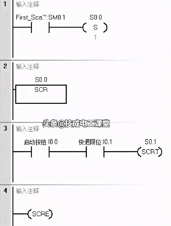
For easier understanding, let’s take the activation of the initial state in sequential control as an example, which is essentially the initialization control.
Using a special auxiliary relay SM0.1, it is connected for one scanning cycle only after the PLC is powered on, so the output actions in the program of this state step are only executed during the first scanning cycle after the PLC is powered on, thus achieving the initialization control of the device.

During the operation of the PLC, many unexpected faults may occur. To avoid the serious consequences of these faults, certain methods and means must be employed to ensure the normal operation of the PLC or to stop its operation. In these cases, conditional termination instructions, stop instructions, and watchdog reset instructions are often used. Let’s explain this with the program in the following figure.
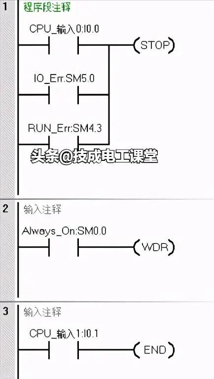
In Program Segment 1, when the I0.0 button is pressed, or the PLC system encounters an IO error, or the PLC detects a program issue, the STOP instruction will be executed. Thus, any of these three situations will trigger the STOP instruction, halting the PLC operation.
In Program Segment 2, when there are many loop programs or interruptions, the PLC’s scanning cycle will be significantly extended, leading to a watchdog error. To ensure the PLC operates normally, we can insert the WDT watchdog reset instruction at appropriate program locations. When the WDT instruction is triggered, it can reset the watchdog.
In Program Segment 3, if a certain part of the program should not run, we can add the END instruction before that part. When the I0.1 button is pressed, the PLC will return to the beginning of the main program to re-scan and execute.

In actual control circuits, unexpected situations may arise. Upon power recovery, the control environment may still be in the previous powered working state, causing the device to resume operation immediately, which could lead to logical errors in device actions and potentially result in accidents. To avoid this situation, it is necessary to implement output prohibition control for some critical devices in the PLC control program.
The output prohibition program upon power recovery uses a special flag SM0.3, which is activated for one scanning cycle, setting M1.0 to 1. Regardless of the states of I2.0 and I2.1, Q1.0 and Q1.1 cannot output.
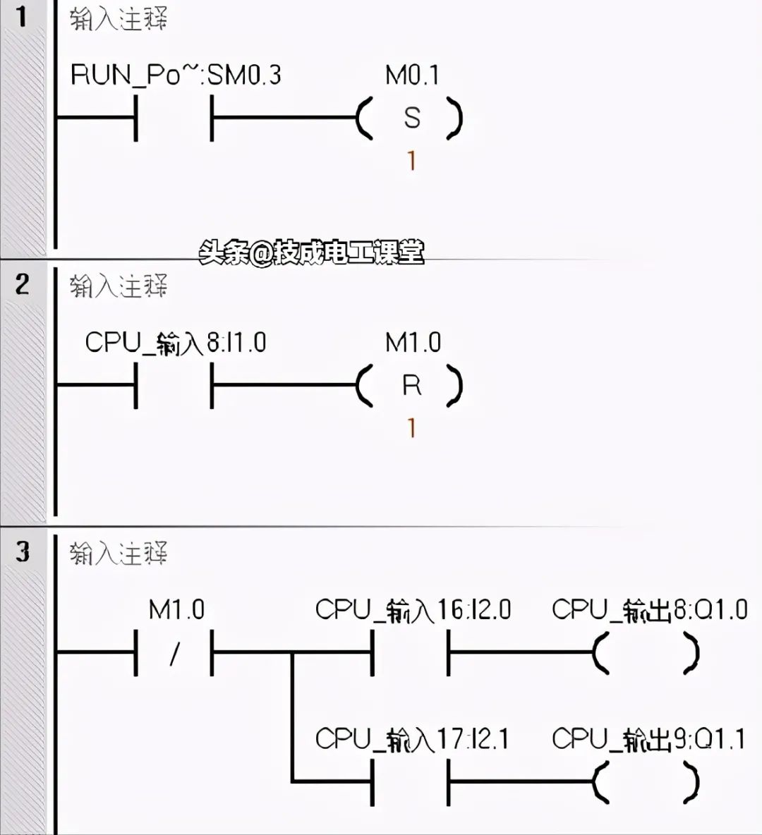
Let’s analyze the execution process. After the PLC powers back on and enters RUN mode, SM0.3 activates for one scanning cycle, setting M1.0 to 1. The normally closed contact M1.0 opens, cutting off the output coils Q1.0 and Q1.1, thereby achieving the goal of prohibiting output.
When the devices controlled by Q1.0 and Q1.1 are ready, for example, when entering the second scanning cycle, the state of I1.0 can be changed by pressing the I1.0 button, resetting M1.0, and restoring the normally closed contact to 1. At this point, control is transferred to I2.0 and I2.1. If I2.0 and I2.1 are activated, then Q1.0 and Q1.1 will output 1.
This avoids the situation where Q1.0 and Q1.1 would output directly if I2.0 and I2.1 were in the ON state after the PLC powers back on.
|
First scanning cycle I1.0=0 |
Second scanning cycle I1.0=1 |
|
SM0.3=1, M1.0=1 I1.0=1, M1.0=1 I2.0=1, Q1.0=0 I2.1=1, Q1.1=0 |
SM0.3=0, M1.0=1 I1.0=1, M1.0=0 I2.0=1, Q1.0=1 I2.1=1, Q1.1=1 |

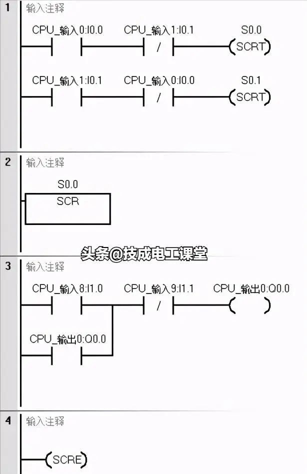
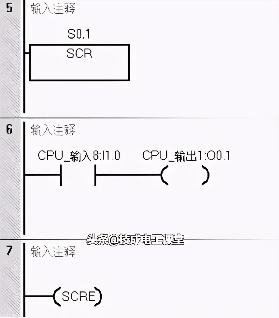
In industrial control, it is often necessary to combine automatic and manual control and provide selection functions. There can also be other conditions to select from, such as returning to the origin, single-step operation, single-cycle loop, and automatic loop, etc. This multi-condition selection function can be implemented using sequential control, or other programming methods such as jumps, main control instructions, etc.
Taking the selection between manual and automatic conditions as an example, when the I1.0 button is ON, the automatic operation program is executed, and when the I0.1 button is ON, the manual operation program is executed.
These are some commonly used basic control designs in the PLC control system. You can make slight modifications based on the specific situation of the control system to apply them. Have you learned it?
(P.S.: The author intentionally left an error in this article; let’s see which student can find it carefully~)
Complete question bank for the 2022 Electrical Engineer Entry Exam (includes answers)
Three essential tools for electrical professionals, easily accessible via WeChat!
[Bookmark] The “path” of a ten-year veteran electrician, the secret to earning over ten thousand a month!
Five major electrical drawing software (CAD, Eplan, CADe_simu…), which one do you choose?
Latest electrical version of CAD drawing software, with a super detailed installation tutorial!
Latest electrical drawing software EPLAN, with a super detailed installation tutorial!
Common problems for beginners using S7-200 SMART programming software (download link included)
Comprehensive electrical calculation EXCEL sheets, automatically generated! No need to ask others for electrical calculations!
Bluetooth headphones, introductory books on electrical engineering/PLC are up for grabs? Come and claim your electrical gifts!
Basic skills in PLC programming: Ladder diagrams and control circuits (includes 1164 practical cases for Mitsubishi PLC)
Still can’t understand electrical diagrams? Grab the basics of electrician diagram reading and simulation software, and quickly get started with theory and practice!
12 free electrician video courses, 10GB of software/e-books, and 30 days of free live electrician courses are being given away!