
The operation of the chip mainly involves manipulating the registers within the chip. Each register has its own unique address mapped in memory, which is what we are operating on. To understand the chip, first look at the timing diagram, then understand the corresponding registers, how they operate, define the necessary ports (which the program can recognize), and write the read and write operation programs.
How to write data into the chip, how to read data out, and which port to input or read from (this is the most important part).
When connecting the chip via a bus, it is essential to understand the protocol of that bus. Chips connected via the I2C bus are mainly controlled through this bus.
1. A 74HC595 in the matrix is used for column selection, while the other two are used for color selection. The matrix is equivalent to a collection of diodes,
one end must be given a high level and the other a low level for the diode to light up. When selecting different ends, different colors light up.
Timer work mode selection: the high four bits set timer T1, and the low four bits set T0. The last two bits of each mode set the work mode. When setting two timers, be careful to use OR (|). When using interrupts, ensure that any necessary resets are done after entering the interrupt.
2. Serial communication: baud rate is generally set using mode 2 (automatic reload initial value), as different devices have varying data processing capabilities. The baud rate is mainly set to accommodate low-speed devices and facilitate communication between them. The interrupt flag must be cleared by software. When setting serial port interrupts, either send or receive can trigger the interrupt function, so be careful to set the interrupt function correctly. (I generally feel it is better to set one function as either a host or a slave.)
To send using interrupts, you need to solve how to enter the interrupt for the first time, so you must send once first; thereafter, you can enter the interrupt. Only one byte can be sent at a time, and the next bit can only be sent after TI is set.
3. The PCF8591AD converter has four channel inputs. When reading from the PCF8591, select which channel to read, and the voltage from that channel will be read. The converted data is stored in the chip and then read out. To read, first write the chip’s address, then write the device’s sub-address (0x40 | channel number), and finally read the data.
4. The DA conversion first writes the device address into the chip, then writes the sub-address (0x40), and then writes the digital value to be converted. The device address is detailed in the chip documentation.
5. For LCD displays, once data is written and displayed, it will continue to display without needing to refresh. To change the display, it must be re-input.
6. For the DS1302 clock chip, when reading data, the first bit of data is read on the eighth falling edge of the clock when writing data, then prepare for the next output. Pay attention to the programming and the placement of return values.
7. For the DS1302, first specify the register, then write data into it. The register addresses are marked in the chip documentation. (I still don’t fully understand the write protection; isn’t it always writable? Why enable write protection?)
(According to the previous masters, after initializing the time, a flag can be set. If this flag exists, there is no need to reinitialize the time. However, if power is lost, the MCU’s RAM cannot retain this flag, so the DS1302’s RAM can be used to store this flag and read it after power is restored. I am also a beginner and plan to use the DS1302 soon. I don’t know if this is correct; I haven’t implemented it yet, but I would like to exchange ideas.)
8. It is best to write initialization as well, to prevent forgetting later. Sometimes when reading or writing, pay attention to whether the least significant bit or the most significant bit is operated first; this can be determined from the timing diagram.
9. For infrared transmission and reception, the receiver determines whether it is a high or low level based on the duration between two falling edges. When writing the program, first use a timer to determine the duration, save it, and then convert it to binary (the writing method of this program is worth studying; it’s very good).
10. Stepper motors: mainly used for switching, the torque of stepper motors decreases as the speed increases. They are mainly used for automatic feeding in machine tools for processing parts. They can also be used in places requiring high precision control.
A stepper motor is an open-loop control element that converts electrical pulse signals into angular displacement or linear displacement. Under non-overload conditions, the motor’s speed and stopping position depend only on the frequency and number of pulse signals, unaffected by load changes. When the stepper driver receives a pulse signal, it drives the stepper motor to rotate a fixed angle in the specified direction, called the “step angle.” Its rotation proceeds in fixed increments. By controlling the number of pulses, the angular displacement can be controlled for accurate positioning; simultaneously, by controlling the pulse frequency, the motor’s speed and acceleration can be adjusted.
11. Servo motors: (servo motor) refer to engines that control the operation of mechanical components within a servo system, serving as a supplementary motor for indirect speed control. Servo motors allow for very precise control of speed and position, converting voltage signals into torque and speed to drive the controlled object. The rotor speed of a servo motor is controlled by the input signal and can respond quickly. In automatic control systems, they serve as actuators and have characteristics such as small electromechanical time constants, high linearity, and starting voltage. They can convert received electrical signals into angular displacement or angular velocity output on the motor shaft. They are divided into two main categories: DC and AC servo motors, with the main feature being that when the signal voltage is zero, there is no self-rotation phenomenon, and the speed decreases uniformly as torque increases. DC motors have a broader range and are commonly found in vehicles.
12. Overview of Chinese characters:
To output Chinese characters on a display or printer, the characters are designed as dot matrix graphics, resulting in the corresponding dot matrix codes (glyph codes).
To represent Chinese characters in a computer, a unified encoding method forms the internal code (such as the national standard code). The internal code is unique (equivalent to the character’s ID number). The encoding formed for the convenience of inputting Chinese characters is called the input code, which belongs to the external code of Chinese characters. Input codes vary due to different encoding methods. The encoding formed for displaying and printing Chinese characters is called the glyph code. The computer finds the glyph code of the Chinese character in the font library through the internal code, achieving the conversion.
Machine internal code
According to the national standard code regulations, each Chinese character has a defined binary code. However, this code conflicts with ASCII code during internal processing in the computer. To resolve this issue, the first bit of each byte of the national standard code is incremented by 1. Since ASCII code uses only 7 bits, this leading “1” serves as a marker indicating that the code is Chinese character information. When the first bit is “1,” the computer interprets it as Chinese character data; when the first bit is “0,” it interprets it as ASCII code. The processed national standard code (internal code) is thus termed machine internal code.
If we replace the dot in the character “口” with “0,” we can visually derive the glyph code for “口”: 0000H 0004H 3FFAH 2004H 2004H 2004H 2004H 2004H 2004H 2004H 2004H 2004H 2004H 3FFAH 2004H 0000H 0000H. When the computer outputs “口,” it first finds the starting address of the display font library, calculates the glyph code for “口” based on its internal code, and then retrieves the glyph code. The binary code with “0” indicates no scan, while “1” indicates a bright point, thus forming the character graphic for “口.”
The glyphs for Chinese characters are arranged in the order of the national standard code and stored in memory as binary files, forming a Chinese character font library, also referred to as a Chinese character library.
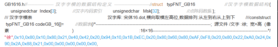
Two encoding methods, see the header file.

This structure is simple: one is the internal code, and one is the dot matrix sequence. Previous dot matrix libraries were arranged in internal code order without needing an internal code index. If only part of the Chinese characters are stored, an internal code index is needed. (The earlier character “徐” is to find the dot matrix sequence for outputting “徐”; this dot matrix sequence is self-written. When using the 1602 display, since the chip has the English dot matrix sequence in its memory, it does not need to be written.) Generally, two bytes are sufficient for the internal code; using an additional byte just adds a trailing zero. Thus, the Chinese character internal code can be directly placed as a string.
13. 12864 LCD:
Each display point corresponds to a binary number, where 1 indicates lit and 0 indicates off. The RAM that stores these dot matrix information is called the display data memory. To display a specific graphic or Chinese character, the corresponding dot matrix information must be written into the appropriate storage unit.
The address counter (AC) of the drawing RAM only automatically increments the horizontal address (X axis) by one. When the horizontal address reaches 0FH, it resets to 00H but does not automatically carry over the vertical address. Therefore, when continuously writing multiple pieces of data, the program must determine whether the vertical address needs to be reset.
14. Drawing RAM (GDRAM)
The drawing display RAM provides 128×8 bytes of memory space. When modifying the drawing RAM, first continuously write the horizontal and vertical coordinate values, then write two bytes of data to the drawing RAM. The address counter (AC) will automatically increment the horizontal address (X address) by one. When the horizontal address is 0XFH, it resets to 00H; it will not automatically increment the vertical address. During the period of writing to the drawing RAM, the drawing display must be turned off.

In C language, defined variables are automatically assigned space, and their addresses correspond to the variable names. Through these names, data can be accessed in memory, and new data can be obtained through calculations. In assembly, the programmer must define storage space and send data to the accumulator for calculations; every step requires the programmer’s intervention. In contrast, these processes are handled by the compiler in C language.
15. Some useful questions and answers
1. How is memory allocation for variables in microcontroller C language handled? Is it the compiler that intelligently adds allocation and deallocation code during the compilation process? The key issue is how to ensure that my program does not have memory overflow errors. If I perform recursive calculations, it is difficult to calculate memory requirements.
2. Are there constraints on variable definitions in microcontroller C language? For example, multiplication and division of floating-point data can be quite complex in assembly, but if written directly in C language, wouldn’t it be overly simple?
3. In the hex file generated by microcontroller C language, are the addresses of instructions and data in ROM automatically allocated by the compiler? Can users allocate them?
Answer 1: Programs written in C language for microcontrollers are first compiled by one program (such as c51.exe). After compilation, the size of the variable storage space is determined, but specific addresses are not yet allocated (addresses are floating). Next, another program (such as a51.exe) links the compiled code, and after linking, specific addresses are confirmed.
If there are too many variables, the compilation will prompt that the data segment is too large. To avoid memory overflow errors, one must consider whether the stack overflows, which relies on experience.
Microcontroller C language generally prohibits recursion; recursive calculations are usually avoided as microcontrollers are not PCs and will affect speed. If recursion is necessary, DSP chips are more suitable. In summary, one must choose the appropriate chip.
Answer 2: The size (bit count) of variables generally matches the bit count of the chip’s accumulator, such as 8 bits for the commonly used 51 microcontroller.
Microcontrollers can define bit variables but cannot define bit arrays. Writing in C language may seem simple, but the generated code volume is the largest. Microcontrollers used for control rarely use floating-point arithmetic, as it is slow, cumbersome, and takes up space. If using DSP chips, which have suitable hardware structures, it will be much better.
Answer 3: Generally, addresses are automatically allocated. It is possible to mix C and assembly language programming, and Keil C online assembly can also be used. Data exchange between the chip and external devices is done through ports.
Copyright statement: This article is an original piece by CSDN blogger “SunMicro nie”.