Sensors can perceive physical quantities such as force, temperature, light, sound, and chemical components, and can transform them according to certain rules into a physical quantity that is easy to transmit and process (usually electric currents, voltages, etc.) or convert them into the on/off states of a circuit. By converting non-electric quantities into electric quantities, measurement, transmission, processing, and control become very convenient.
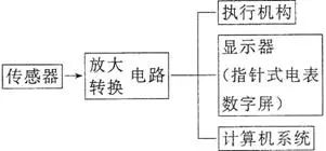
Sensors typically perceive non-electric quantities such as pressure, temperature, displacement, concentration, speed, and acidity, while they usually output electric quantities such as voltage values, current values, and charge amounts. These output signals are very weak and typically need to be amplified before being sent to the control system to generate various control actions, as illustrated in the diagram.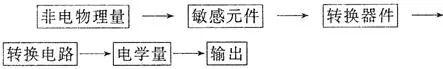
Photoresistor – Fire Alarm
1. The resistance of a photoresistor changes when illuminated, allowing the photoresistor to convert the intensity of light into the size of this electric quantity.
2. The resistance of the photoresistor decreases with increased illumination.
The photoresistor is generally made of semiconductor materials. When the semiconductor material is illuminated or the temperature rises, more electrons gain energy and become free electrons, while more holes are also formed, thus significantly enhancing its conductivity.
Temperature Sensor Application – Electric Iron
Temperature sensors can be made from thermistors and metal thermistors, which can convert thermal signals into electrical signals for automatic control.
(1) Structure of the electric iron:
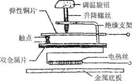
(2) Automatic temperature control principle of the electric iron:
It is equipped with a bimetallic temperature sensor, as shown in the above diagram.
Under normal temperature, the upper and lower contacts should be in contact. However, when the temperature is too high, due to the different thermal expansion coefficients of the bimetallic strip, the upper metal expands more than the lower metal, causing the bimetallic strip to bend downwards, separating the contacts, thereby cutting off the power and stopping heating. After the temperature drops, the bimetallic strip returns to its original state, reconnecting the circuit for heating, and this process continues, achieving automatic temperature control.
Setting different temperatures is required for ironing cotton-linen clothes and silk clothes. How is this achieved using the temperature adjustment knob?
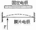
Capacitive Pressure Sensor
When the pressure F to be measured acts on the movable diaphragm electrode, it can cause deformation of the diaphragm, leading to a change in capacitance. If the capacitor is connected in series with a sensitive ammeter and a power supply to form a closed circuit, when F presses the diaphragm electrode upwards, the capacitance of the capacitor will increase. If the ammeter shows a reading, then the pressure F has changed (as shown in the diagram).
In comparison, the metal thermistor has good chemical stability and a wide temperature measurement range, while the thermistor has better sensitivity.
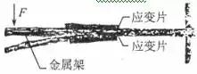
Force Sensor Application – Electronic Scale
(1) Composition: Composed of a metal frame and strain gauge.
(2) Working Principle of the Electronic Scale: As shown in the diagram, the beam element made of spring steel is fixed at one end. A strain gauge is attached to the upper and lower surfaces of the beam, and a force F is applied at the free end of the beam, causing it to bend. The upper surface stretches, and the lower surface compresses. The resistance of the strain gauge on the upper surface increases, while that on the lower surface decreases. The greater the force F, the larger the bending deformation, and the greater the change in resistance of the strain gauge. If the current flowing through the strain gauge is kept constant, the voltage across the strain gauge on the upper surface increases, while that on the lower surface decreases, and the sensor outputs the difference in these two voltages. The greater the external force, the larger the output voltage difference.
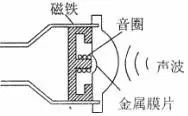
Sound Sensor Application – Microphone
(1) Dynamic Microphone Principle
A microphone is a device that converts sound into electrical signals. The diagram below shows the structural principle of a dynamic microphone, which is made using the phenomenon of electromagnetic induction. When sound waves cause the metal diaphragm to vibrate, the coil (called the voice coil) attached to the diaphragm also vibrates. In the diagram, the voice coil vibrates in the magnetic field of a permanent magnet, generating induced current (electrical signal). The magnitude and direction of the induced current vary, and the amplitude and frequency of the variations are determined by the sound waves. This signal current is amplified by an amplifier and sent to a speaker, which produces amplified sound.
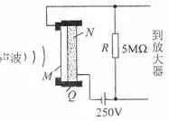
(2) Capacitive Microphone Principle:
As shown in the diagram, Q is the insulating bracket, the thin metal film M and the fixed electrode N form a capacitor, which is charged by a DC power supply. When sound waves cause the diaphragm to vibrate, the capacitance changes, resulting in a varying current in the circuit, thereby outputting a voltage across the resistor R that corresponds to the sound variations. Its advantage is good fidelity.
(3) Electret Microphone
① Polarization Phenomenon: When a dielectric is placed in an electric field, positive and negative charges appear on its front and back surfaces, respectively.
② Electret: Some dielectrics maintain their polarized state even after the external electric field is removed. Such materials are called electrets.
③ Principle: Similar to the capacitive microphone, but the internal sensing element is an electret plastic film.
④ Features: Small size, lightweight, low cost, high sensitivity, and low operating voltage, requiring only 3-6V.
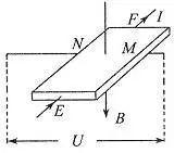
Hall Element
1. As shown in the diagram, a conductor plate with thickness d is placed in a uniform magnetic field with magnetic induction strength B. When a constant current I flows through the conductor plate, a potential difference appears on the left and right sides of the plate. This phenomenon is called the Hall effect. Four electrodes E, F, M, N are made on this rectangular semiconductor, which can convert the magnetic induction strength into an electrical quantity (voltage).
2. Hall Voltage 
① Where k is a proportionality constant known as the Hall coefficient, which is related to the material of the thin slice.
② For a Hall element, d and k are constants. If I is kept constant, then changes proportionally with B, thus the Hall element is also known as a magnetic-sensitive element.
3. Working Principle
The Hall element is designed using the Hall effect. A rectangular semiconductor sheet has an electrode drawn out on its front, back, left, and right sides. When current I flows along the EF direction and a uniform magnetic field B is applied perpendicular to the sheet, a potential difference U appears between MN. Let the thickness of the sheet be d, the length in the EF direction be l1, and the length in the MN direction be l2. Charged particles in the sheet are deflected by the magnetic force, causing the potential on the N side to be higher than that on the M side, creating an electric field within the semiconductor. The charged particles are simultaneously acted upon by the electric field force. When the magnetic force and electric field force balance, the potential difference between MN reaches a constant value.

According to the microscopic interpretation of current
Overall, we have:

Let where n is the number of charged particles per unit volume of the material, and q is the charge of a single charged particle.
Thus
It can be seen that U is proportional to B, which is why the Hall element can convert magnetic quantities into electrical quantities.
1. The diagram below shows a simple circuit containing a logic circuit, where L is a small light bulb. When light shines on the resistor, its resistance will become much smaller than R, which of the following statements is correct? ( )
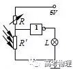
A. This logic circuit is a NOT gate; when the resistor is illuminated, the light bulb L does not light up.
B. This logic circuit is a NOT gate; when the resistor is illuminated, the light bulb L lights up.
C. This logic circuit is an AND gate; when the resistor is illuminated, the light bulb L does not light up.
D. This logic circuit is an OR gate; when the resistor is illuminated, the light bulb L lights up.
2. The diagram shown is a partial circuit diagram of a fire alarm system, where R3 is a sensor made of semiconductor thermistor material. The display in the duty room is an ammeter in the circuit, and a, b connect the alarm. When a fire occurs at the location of the sensor R3, the changes in the current I of the display and the voltage U across the alarm are ( ).
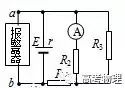
A. I increases, U increases.
B. I increases, U decreases.
C. I decreases, U decreases.
D. I decreases, U increases.
1. B
2. C
Do you have any questions about sensors?
Feel free to leave a message and discuss with us.
▐ Tags: Basic Knowledge Analysis.
▐ Disclaimer: This article is created by the Gaokao Physics (ID: gkwl100) content team. Please contact us for authorization before reprinting.