
Neuro and Evil fun time pid:126363594 by:Wimo
Yes, that’s right, I2C has also been discussed in the Microelectronic System
Click here to view the Microelectronic System review: I2C
Background Knowledge
Parallel Transmission and Serial Transmission
- Parallel Transmission
- Transmits multiple bits at once, usually using multiple data lines simultaneously.
- Serial Transmission
- Transmits one bit at a time, usually using a single data line in sequence.
Asynchronous Transmission and Synchronous Transmission
- Asynchronous Transmission
- The sending and receiving devices do not need to share a clock signal; the timing of data transmission is controlled by start and stop bits.
- For example, USB, UART
- Synchronous Transmission
- The sending and receiving devices share a clock signal; the timing of data transmission is controlled by the clock signal.
- For example, I2C, SPI
Inter Integrated Circuit (I2C)
Overview
I2C is a synchronous serial communication protocol developed by Philips in the early 1980s, primarily used to connect microcontrollers and various peripherals. The design goal of I2C is to achieve low-speed, short-distance communication, suitable for various applications in embedded systems.
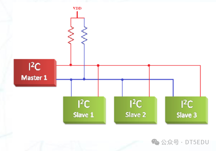
I2C follows a master-slave architecture, where the master device initiates communication and controls data transmission, while the slave devices respond to the master’s requests. An I2C bus typically has one or more slave devices and one or more master devices, with only one master device active at any given time.
Each slave device has a unique address, and the master device selects the slave device to communicate with using this address. The slave device determines if it is its address by listening to the data on the bus; if it is, it responds to the master’s request. This addressing method limits the number of slave devices, typically allowing up to 127 slave devices in 7-bit addressing mode (0x00 address is reserved for the bus controller). In 10-bit addressing mode, more slave devices can be connected, but this is less commonly used in practice.
The I2C protocol uses two lines for communication: SDA (Serial Data Line) and SCL (Serial Clock Line). SDA is used for data transmission, and SCL provides the clock signal. Both SDA and SCL lines are open-drain outputs, meaning they are pulled high (Vcc) through pull-up resistors, and devices can pull the line low (GND) during data transmission. This design allows multiple devices to share the same bus, and only one device can send data at a time on the bus, avoiding conflicts.
Since both input and output occur through the SDA line, I2C is a half-duplex protocol.
Transmission
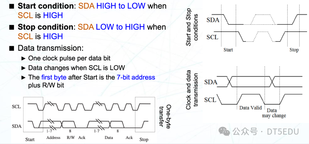
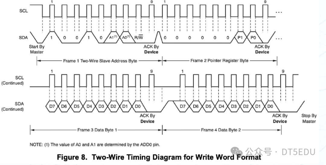
- Start Condition
- SCL remains high
- SDA transitions from high to low
- Stop Condition
- SCL remains high
- SDA transitions from low to high
- Data Transmission
- The SDA line changes when SCL is low, and remains unchanged when SCL is high
- Data on the SDA line is sampled when SCL is high
All I2C data transmissions are byte-oriented, and there is no limit to the number of bytes in a message. After each byte, the receiver must send an ACK signal to confirm receipt.
The first byte consists of a 7-bit address and a 1-bit read/write bit. A read/write bit of 0 indicates a write operation, while a 1 indicates a read operation. The receiver sends an ACK signal after receiving the address byte, indicating it is ready to receive data.
I2C in MBed OS
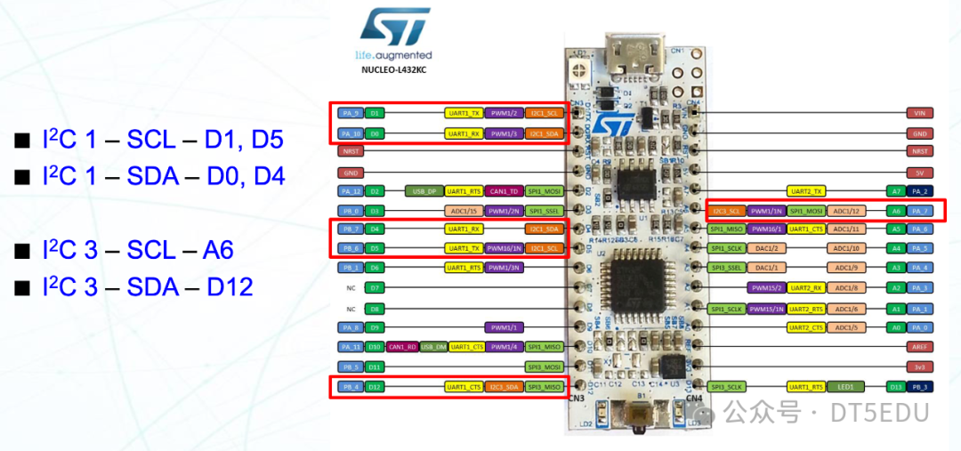
The development board we are using, <span>NUCLEO L432KC</span>, also supports I2C communication. It has <span>I2C1</span> and <span>I2C3</span> controllers, with corresponding pins as shown in the figure.
In <span>MBed OS 6</span>, there are APIs for I2C master and slave.
I2C Master API
<span>I2C(PinName sda, PinName scl)</span>- Creates an I2C object, specifying the SDA and SCL pins
<span>int read(int address, char *data, int length, bool repeated = false)</span>- Reads data from the specified address
<span>int write(int address, const char *data, int length, bool repeated = false)</span>- Writes data to the specified address
<span>int write(int data)</span>- Writes a byte of data to the I2C bus
<span>int read(int ack)</span>- Reads a byte of data from the I2C bus
<span>void frequency(int hz)</span>- Sets the I2C frequency
<span>void start()</span>- Starts I2C communication (sends start condition)
<span>void stop()</span>- Stops I2C communication (sends stop condition)
Sample program (from MBed OS 6: I2C)
/*
 * Copyright (c) 2014-2020 Arm Limited and affiliates.
 * SPDX-License-Identifier: Apache-2.0
 */

#include "mbed.h"

// Read temperature from LM75BD

I2C i2c(I2C_SDA, I2C_SCL);

const int addr7bit = 0x48;      // 7 bit I2C address
const int addr8bit = 0x48 << 1; // 8bit I2C address, 0x90

int main()
{
    char cmd[2];
    while (1) {
        cmd[0] = 0x01;
        cmd[1] = 0x00;
        i2c.write(addr8bit, cmd, 2);

        ThisThread::sleep_for(500);

        cmd[0] = 0x00;
        i2c.write(addr8bit, cmd, 1);
        i2c.read(addr8bit, cmd, 2);

        float tmp = (float((cmd[0] << 8) | cmd[1]) / 256.0);
        printf("Temp = %.2f\n", tmp);
    }
}
I2C Slave API
<span>I2CSlave(PinName sda, PinName scl)</span>- Creates an I2C slave object, specifying the SDA and SCL pins
<span>void frequency(int hz)</span>- Sets the I2C frequency
<span>int receive()</span>- Confirms whether the address on the bus matches
- Return values:
<span>0</span>: Address does not match<span>1</span>: Address matches, master is writing data<span>2</span>: Address matches, master is reading data
<span>int read(char *data, int length)</span>- Reads data from the I2C bus
<span>int write(const char *data, int length)</span>- Writes data to the I2C bus
<span>void address(int address)</span>- Sets the I2C slave address
<span>void stop(void)</span>- Stops I2C communication, resetting to the waiting state
Sample program (from MBed OS 6: I2C Slave)
/*
 * Copyright (c) 2006-2020 Arm Limited and affiliates.
 * SPDX-License-Identifier: Apache-2.0
 */
#include <mbed.h>

#if !DEVICE_I2CSLAVE
#error [NOT_SUPPORTED] I2C Slave is not supported
#endif

I2CSlave slave(D14, D15);

int main()
{
    char buf[10];
    char msg[] = "Slave!";

    slave.address(0xA0);
    while (1) {
        int i = slave.receive();
        switch (i) {
            case I2CSlave::ReadAddressed:
                slave.write(msg, strlen(msg) + 1); // Includes null char
                break;
            case I2CSlave::WriteGeneral:
                slave.read(buf, 10);
                printf("Read G: %s\n", buf);
                break;
            case I2CSlave::WriteAddressed:
                slave.read(buf, 10);
                printf("Read A: %s\n", buf);
                break;
        }
        for (int i = 0; i < 10; i++) {
            buf[i] = 0;    // Clear buffer
        }
    }
}
</mbed.h>
Using I2C to Drive TMP102
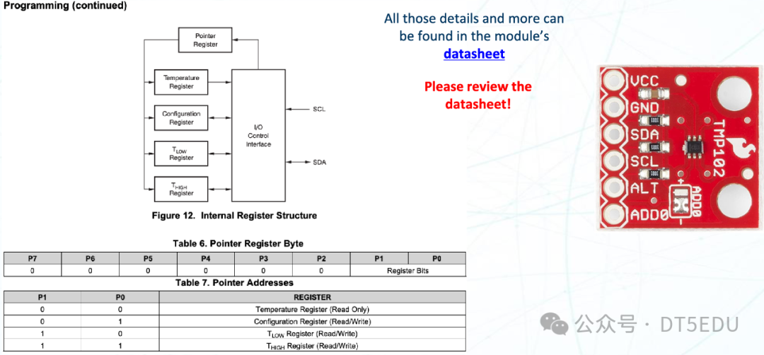
TMP102 is a digital temperature sensor with an I2C interface. It can measure temperature and transmit data to the master device via the I2C bus. We can refer to the TMP102 datasheet to understand its operation and register configuration.
Then, we can drive the TMP102 using the I2C interface in MBed OS:
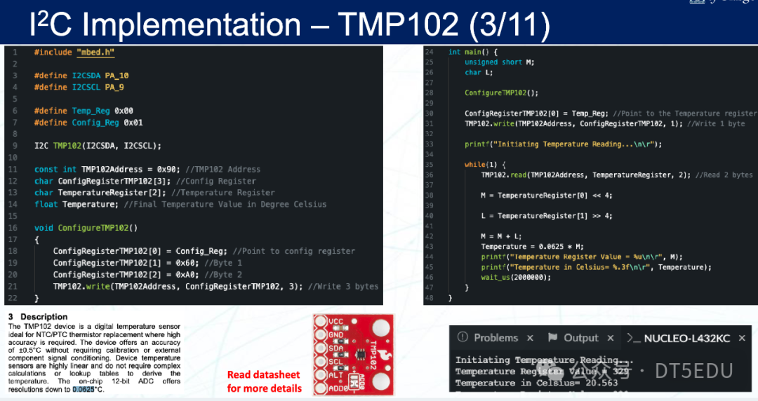
During the configuration of TMP102, we first sent the address 0x01, indicating that we want to configure the TMP102’s configuration register. Then we sent 0x60 and 0xA0, which correspond to the first and second bytes of the configuration register.
The format of the configuration register is as follows:
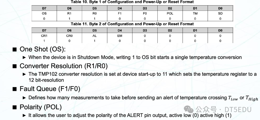
- One-Shot (OS)
- 0: Continuous conversion
- 1: One-time conversion
- Converter Resolution (R1/R0)
- 00: 9-bit resolution
- 01: 10-bit resolution
- 10: 11-bit resolution
- 11: 12-bit resolution
- Fault Queue (F1/F0)
- Maximum number of errors allowed when the temperature exceeds the set value
- Polarity (POL)
- 0: Active low
- 1: Active high
- Thermostat Mode (TM)
- 1: Interrupt mode
- AL is set when the temperature exceeds
- AL is reset when the temperature falls below
- 0: Comparator mode
- AL is set when the temperature exceeds
- AL is reset during a read operation
- Shutdown Mode (SD)
- 0: Active mode
- 1: Sleep mode
- Conversion Rate (CR1/CR0)
- 00: 0.25 Hz
- 01: 1 Hz
- 10: 4 Hz
- 11: 8 Hz
- Alert (AL)
- Reading the AL bit provides status information for comparator mode
Similarly, we can send different addresses to write to different registers.
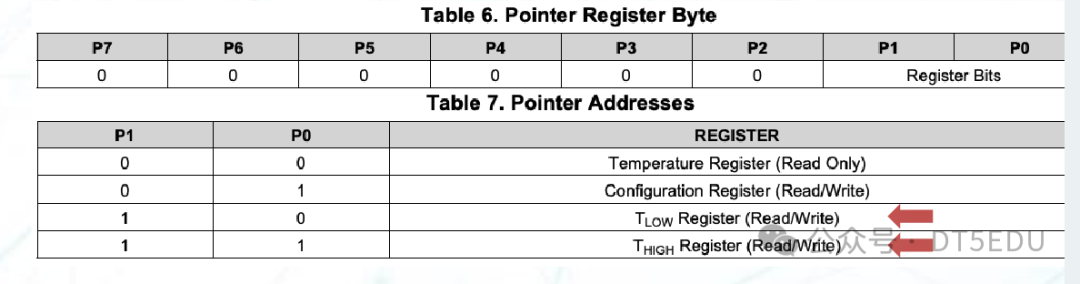
<span>0x00</span>: Read-only temperature register<span>0x01</span>: Writable configuration register<span>0x02</span>: Writable register<span>0x03</span>: Writable register
Finally, we implement the corresponding functionality using MBed OS:
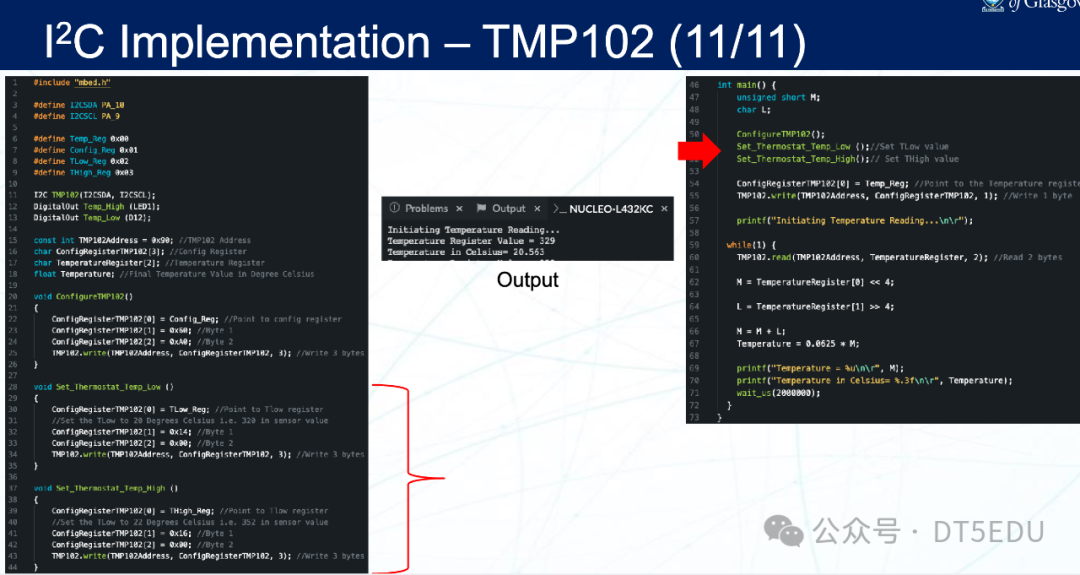
Thus, we have completed the task of driving TMP102 using I2C.