▼For more exciting recommendations, please follow us ▼In daily life, we often encounter situations where devices lose power, such as mobile phones, smart wristbands, and computers; however, the stored information does not get lost, such as phone numbers, text messages, notes, WeChat, QQ messages, etc., which are all preserved. These items only disappear after a factory reset.This is because these devices have a “power loss retention” component, such as hard drives and USB drives, which are characterized by the ability to retain information even when power is lost, similar to the memory function of the human brain.Such components are also very common in the industrial field, typically including EEPROM and FLASH. Their common feature is that they are read/write and retain data during power loss;The difference is that EEPROM does not require erasure before writing, while FLASH must be erased before writing; EEPROM generally uses the I2C bus for communication, while FLASH typically uses the SPI bus.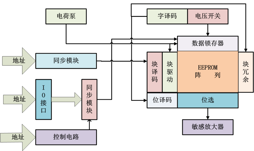 EEPROM Memory System Architecture DiagramToday, I will discuss the I2C bus:
Bit Transmission
The I2C bus is a bidirectional two-wire synchronous serial bus developed by Philips, enabling effective control between ICs. It requires only two lines (SDA and SCL) to transmit information between devices connected to the bus.Data on the I2C bus is transmitted bit by bit. SCL is the clock line, and SDA is the data line; when the SCL clock line is high, the level on the SDA data line cannot be modified, and when the SCL clock line is low, the level on the SDA data line can be high or low.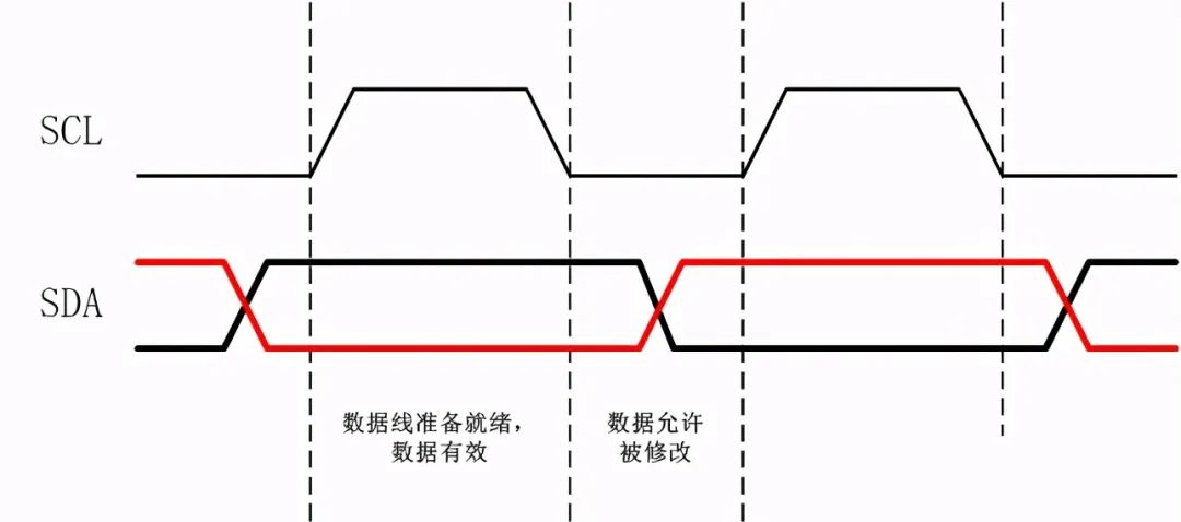 Bit Transmission of the I2C BusStart Condition:When SCL is high, SDA switches from high to low; indicating the start of data transmission.Stop Condition:When SCL is high, SDA transitions from low to high; indicating the end of data transmission.Idle Condition:When both SDA and SCL lines of the I2C bus are high; indicating an idle state.
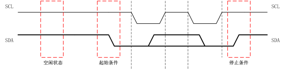 Start and Stop Conditions
Data Transmission
Byte TransmissionWhen sending data, the host first sends a start signal on the I2C bus, then switches the SDA signal to output mode, and sends the 8-bit data sequentially from high to low;After sending, the host switches the SDA signal to input mode, waiting for an ACK or NAK response from the slave before sending the next data.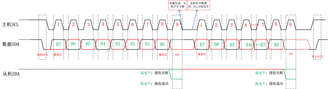 I2C Bus Data TransmissionSlave AddressIn the I2C bus system, each device has a fixed address, generally determined by the chip’s A0, A1, and A2. The slave address byte consists of seven address bits (D7-D1) and one direction bit (D0).The D7-D4 bits of the device address are generally fixed by the manufacturer to 1111, while the remaining D3, D2, and D1 are connected to the chip’s A2, A1, and A0 to determine; D0 is 0x00 for write and 0x01 for read. This is why you often see addresses like 0xA0 and 0xA1 in examples.
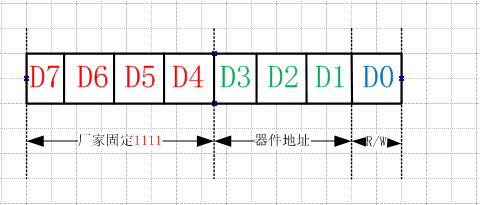 EEPROM Device Address
Read/Write Process
1. Write Data Process1. The host sends a stop signal on the I2C bus to prevent data write failure due to a busy bus.2. The host sends a reset signal on the I2C bus to ensure the bus is idle before writing data.3. The host sends a start signal on the I2C bus to initiate a data write.4. The host sends the I2C slave address and write mode (W/R=0) signal, waiting for a response from the slave.5. After receiving the ACK response, the host begins writing multiple bytes, waiting for an ACK response after each byte written.6. After receiving the ACK response, the host sends a stop signal on the I2C bus to ensure the bus is idle.2. Read Data Process1. The host sends a stop signal on the I2C bus to prevent data read failure due to a busy bus.2. The host sends a reset signal on the I2C bus to ensure the bus is idle before reading data.3. The host sends a start signal on the I2C bus to initiate a data read.4. The host sends the I2C slave address and read mode (W/R=1) signal, waiting for a response from the slave.5. After receiving the ACK response, the host begins reading multiple bytes, sending an ACK response to the slave after each byte read.6. After receiving the ACK response, the host sends a stop signal on the I2C bus to ensure the bus is idle.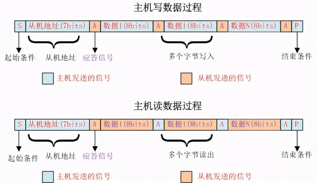 Host Read/Write Data Process
Conclusion
The I2C bus is widely used in embedded applications; virtually all power electronic devices utilize this bus.Based on my years of work experience, I have documented my understanding of it. If there are any inaccuracies, I hope everyone can point them out. This concludes today’s discussion on the I2C bus, and I hope you enjoyed it. 👉 Is it return 1 or return 0? No need to be too serious👉How to systematically design hardware circuits? Sharing some experiences👉The Father of Computers: The Life of Genius John von Neumann👉Is the CAN bus a digital signal or an analog signal?👉Microcontroller Download Files: The Difference Between HEX and BIN Files