[Note: The following content is based on the simulation programming of Huichuan PLC (easy52x) using AutoShop. Other brands of PLCs may vary slightly. This article aims to help you quickly get started with STL and SFC programming.]
Recommended Learning Sequence
Ladder Diagram –> STL Step Ladder Diagram –> SFC Sequential Function Chart
STL Step Ladder Diagram
The STL Step Ladder Diagram differs from a regular ladder diagram in that it can divide a complete operation process into several steps. Each step represents a state, and when certain conditions are met, it can switch from the current state to the next state. In this control method, only the instructions in the current state will be executed; instructions in other states will not be executed.
STL Step Ladder Diagram Instructions
The STL Step Ladder Diagram instructions consist of only two instructions: STL and RET. Instructions from regular ladder diagrams can also be used.
STL Instruction
Function: Indicates entry into a certain state S; the program jumps tothe sub-bus, meaning that the program will only execute the instructions at the current state S, and instructions at other states will not be executed.
Format: STL Sn
Sn represents the state, such as S0, S1, etc.;
Example: STL S0 // Enter state 0;
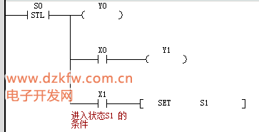
The thick vertical line on the left is themain bus, equivalent to the main program, while the thinner vertical line on the right is thesub-bus, equivalent to the execution process under state S0;
RET Instruction
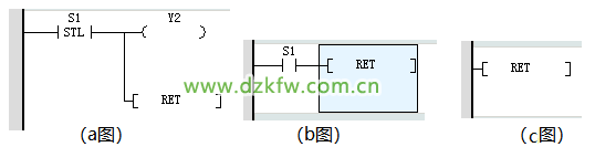
Function: Indicates the end of the step ladder diagram program; the program jumps to the main bus and continues executing the non-step instructions or step instructions that follow (if any);
Format: RET
(Note: In AutoShop software, RET must be directly connected after the STL instruction, as shown in the figure below. Figures b and c will report errors!)
 STL Step Ladder Diagram Programming State Numbering
To smoothly convert the STL Step Ladder Diagram into an SFC Sequential Function Chart, it is recommended to use the state number rules of SFC: S0~S9 for initial state soft elements, S10~S19 for special purposes, and other ordinary states can use S20~S889, etc.;
There are no strict restrictions on state numbers in the STL step diagram, and initial state numbers set outside S0~S9 can also be used; however, the SFC Sequential Function Chart has strict requirements, where the initial state number can only be S0~S9, and other ordinary step state numbers can only be S10~S889, etc.;
Entering the Initial State
Since step states S generally use normally open contacts, the PLC will not directly enter the initial state after startup. Therefore, we need to set it in advance to enter the initial state. The simplest way is to use the SET instruction to directly set it to the initial state;
For example:
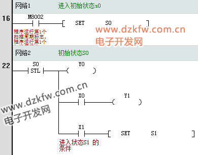
M8002 soft element is the flag for the first scan cycle of the program. The first scan cycle of the program is ON, and the subsequent cycles are OFF. This means that when the program runs the first scan cycle, M8002 is energized, S0 is set to 1, and the subsequent normally closed contact of the initial state S0 is also energized, thus entering the initial state S0;
Composition of the Step Program
A complete STL Step Ladder Diagram starts with the STL instruction and ends with the RET instruction; the intermediate program will only switch between states, and switching from the current state to the next state requires meeting the jump conditions;
A complete step program generally consists of a regular ladder diagram + STL Step Ladder Diagram; a typical example is as follows: the regular ladder diagram is used to control entry into the step initial state, and the STL Step Ladder Diagram is used to implement the functions of different states;
That is: regular ladder diagram ==> [STL–step–RET]
In other words, the STL Step Ladder Diagram can also intersperse regular ladder diagrams, but it must follow the rule: the regular ladder diagram must be inserted at the end of an STL Step Ladder Diagram, not in the middle;
That is: regular ladder diagram ==> [STL–step–RET] ==> regular ladder diagram ==> [STL–step–RET];
Some Rules for STL Step Ladder Diagram Programming (Verify Yourself)
1) The same output can be used under different states S without causing double coil outputs;
2) During a scan cycle, when switching from the current state to the next state, there will be a moment when two states are simultaneously energized; the solution is to set interlocks;
3) Adjacent states cannot use the same timer;
4) State transitions can also use the OUT instruction besides the SET instruction, but in SFC, the OUT instruction is used for transferring to separated states;
5) STL instructions cannot be used in interrupts and subroutines;
6) It is best not to use jump instructions in STL step programs, not because they are prohibited, but because the logic will become too complex;
Running Light Example
For a simple example, there are three lights A, B, and C, with the running requirement: when the start button is pressed, A, B, and C light up in sequence for 3 seconds, then repeat, and when the stop button is pressed, the system stops running!
The following is the complete step program, which is only to achieve simulation functionality, without optimization or other considerations;
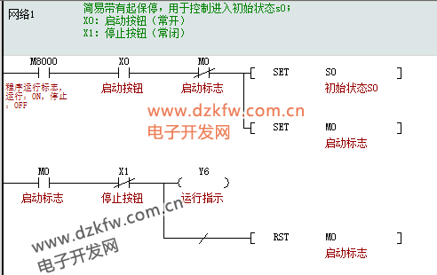
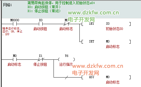
Network 1: After powering on, when the “Start Button” X0 is pressed, S0 is set (entering the initial state), M0 is set (since it is a SET instruction, it will remain set), and the “Running Indicator” light Y6 is on; during operation, when the “Stop Button” is pressed, M0 is reset, and the “Running Indicator” light Y6 is off;
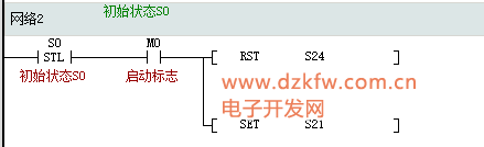
Network 2: is the initial state S0;
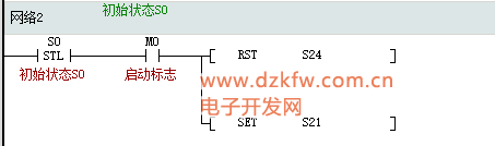
When the “Start Button” is pressed, it will enter the initial state. In the initial state, it is used to reset state S24 and enter the next state S21; resetting S24 is necessary because during operation, when the “Stop Button” is pressed, it will enter the stop state S24, and S24 will be set. Therefore, when the “Start Button” is pressed again to run the system, S24 needs to be reset;
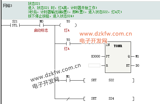
Network 3: is state S21;
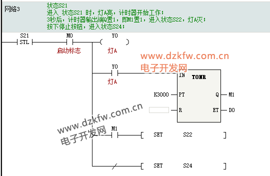
During operation, after entering state S21, both the S21 normally open contact and the M1 normally open contact are set to conduct, turning on light A. The illumination of light A starts the timer, and after 3 seconds, the timer output port Q is set, that is, M1 is set, and the M1 normally open contact closes, entering state S22, while the S21 normally open contact opens, and the function of state S21 becomes invalid (light A goes out, timer resets);
When the “Stop Button” is pressed, the M0 normally open contact opens, light A goes out, the timer resets, and it enters state S24 (stop state);
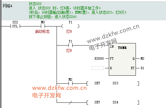
Network 4: is state S22, analyzed in the same way as state S21;
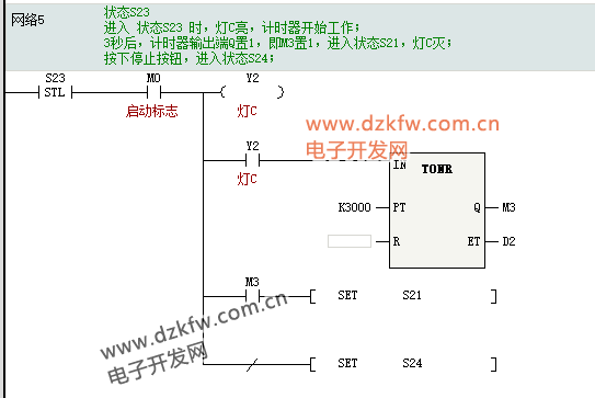
Network 5: is state S23, analyzed in the same way as state S21;
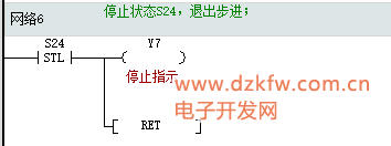
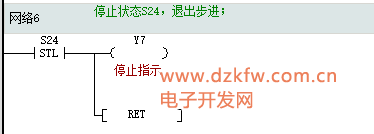
Network 6: is state S24 (stop state); in this state, the “Stop Indicator” light is on, and then it exits the step and returns to the main program to continue execution;
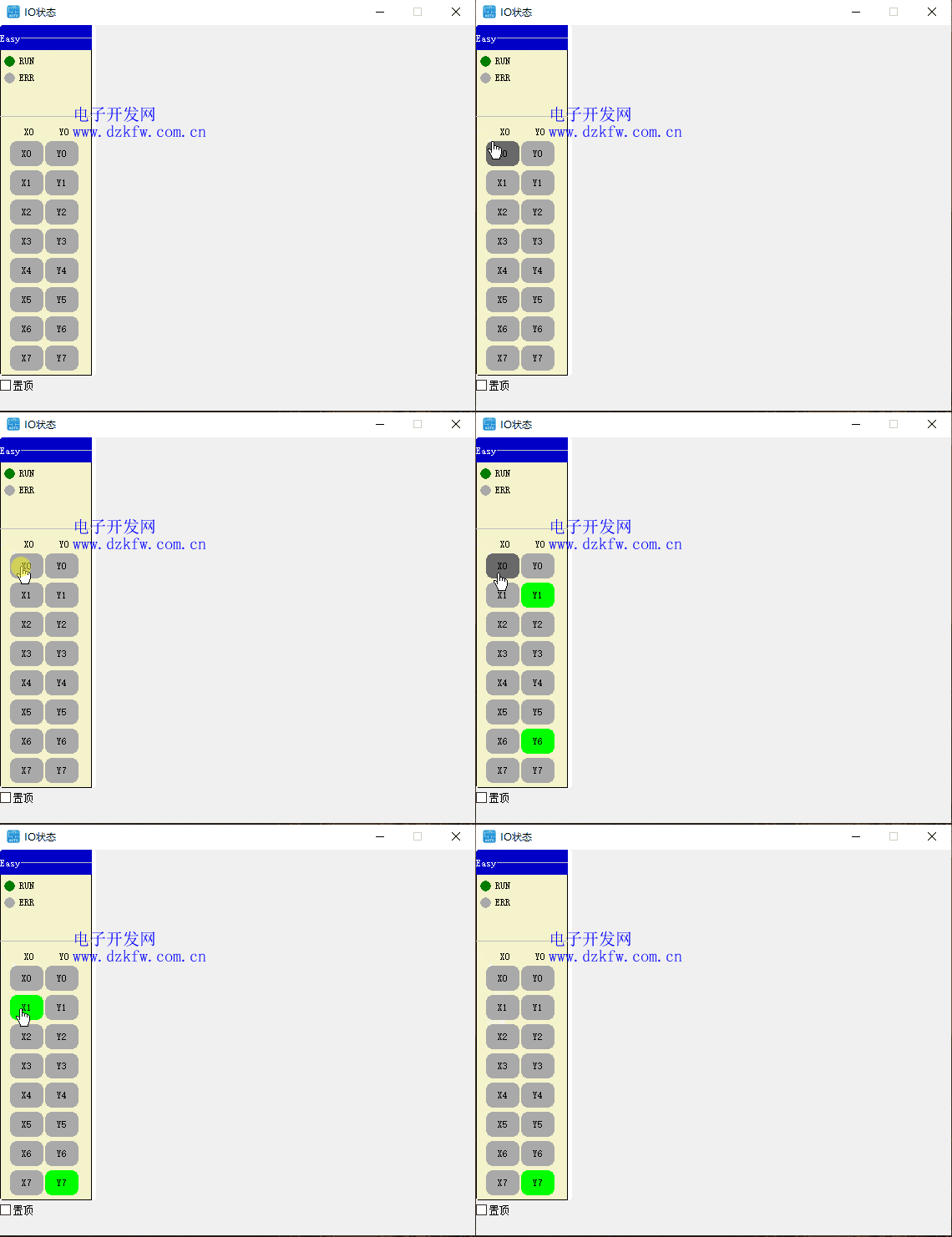
 Simulation Results of the Running Light Example
Effect after pressing and releasing the start button (X0): Running indicator light (Y6) is on; lights A (Y0), B (Y1), and C (Y2) light up in sequence for 3 seconds;
Effect after pressing and releasing the stop button (X1): Running indicator light (Y6) is off, stop indicator light (Y7) is on;
SFC Sequential Function Chart
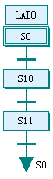
The SFC Sequential Function Chart is more intuitive than the STL Step Diagram; it usesgraphical symbols to display the entire process. It can be said that if you can write an STL Step Diagram, you can basically write an SFC Sequential Function Chart; SFC simply places all the instructions to be executed in a certain state into a “step symbol,” while the transition conditions are placed in the “state transition condition diagram”;
Below is a display of the style of the SFC Sequential Function Chart:
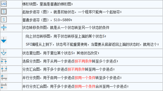
 Symbol Definitions
As for whether to call them symbols or blocks, just use whichever is more convenient!
Characteristics of SFC Programming
1) Like the STL Step Ladder Diagram, the SFC Sequential Function Chart also requires setting the state properly to enter the initial state; these ladder diagrams used to trigger entry into the initial state can be placed in
to complete; the simplest way is to drive the SET instruction S0 into the initial state through M8002;
2) The initial state number can only be S0~S9, and other ordinary step state numbers can only be S10~S889, etc.;
3) State numbers in SFC cannot be reused;
4) SFC can implement complex branching processes, as shown in the figure below:
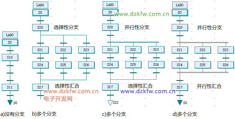 SFC Example
To facilitate comparison with the STL Step Diagram, we will take the previous Running Light Example and convert it into an SFC Sequential Function Chart. Their overall correspondence is shown in the figure below:
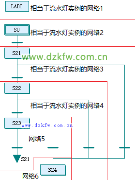 Running Light Example Conversion of Network 1
Running Light Example STL Step Diagram Network 1 before replacement:
After replacement:
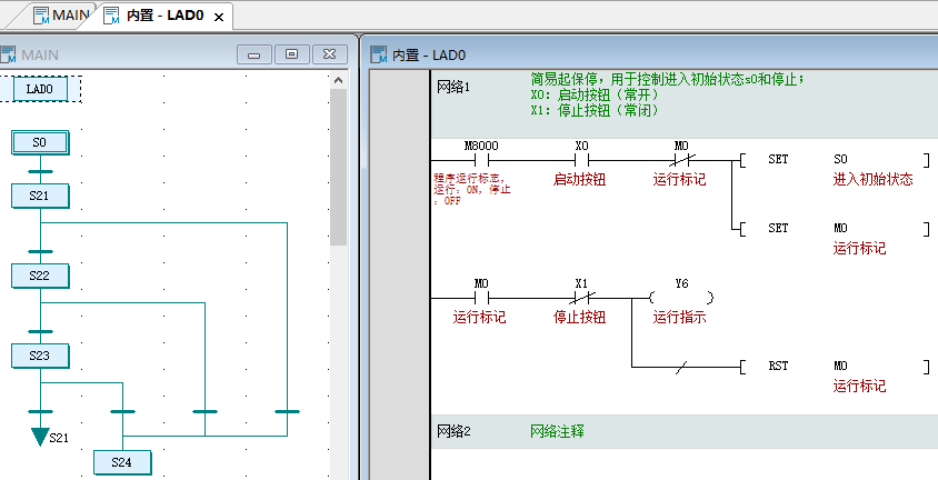
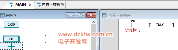
Running Light Example Network 1 is equivalent to LAD0 in the SFC Sequential Chart, where the built-in ladder diagram of LAD0 is shown below, which is exactly the same as the content of Network 1 of the Running Light Example;
Running Light Example Conversion of Network 2 (Initial State S0)
Running Light Example STL Step Diagram Network 2 (Initial State S0) before replacement:
After replacement:


 Running Light Example Conversion of Network 3 (State S21)
Running Light Example STL Step Diagram Network 3 (State S21), Network 4 (State S22), and Network 5 (State S23) are converted into SFC Sequential Charts in the same way. Below, we take the conversion of Network 3 (State S21) as an example;
Running Light Example STL Step Diagram Network 3 before conversion:
After conversion:
From the above figure, it can be seen that except for the state transition instructions that have been removed, everything else remains in the built-in ladder diagram of state S21;
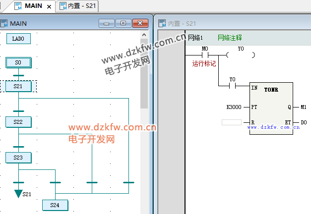
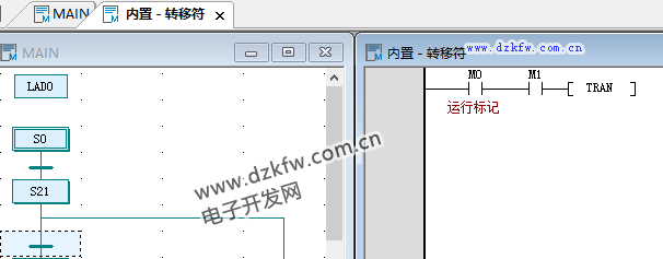
The firststate transitionSET S22 instruction condition (M0 and M1 normally open contacts) has been replaced with the left side “state transition symbol”✝;
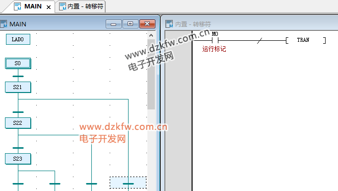
The secondstate transitionSET S24 instruction condition (M0 normally open contact and NOT instruction) has been replaced with the right side “state transition symbol”✝;
 Running Light Example Conversion of Network 6 (State S24)
Running Light Example STL Step Diagram Network 6 before replacement:
After replacement:
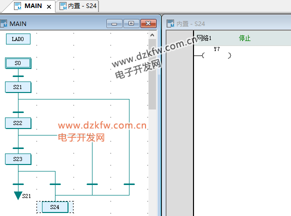
Summary: The regular output instructions as the execution process of this state are retained in the step symbol, while the SET output instructions for state transitions become “state transition symbols,” with the transition conditions being the execution conditions of the SET instructions, except for the STL instruction4545;
SFC Example Simulation Results
The simulation results of the SFC Sequential Function Chart are the same as those of the STL Step Ladder Diagram;
<img src=”https://mmbiz.qpic.cn/sz_mmbiz_png/h1KwVFrY69AiblfA3QJQpK0zWVPLNhicGjxUwZBicG49dwPicex49VicK4MpFLmBgwbTVI5oS1ibpmKIG408IK2oMmrg/640?wx_fmt=png&from=appmsg#imgIndex=26″