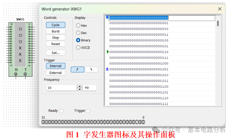
Word Generator(Word Generator) is used to generate predefined digital data sequences, inputting a series of parallel or serial data into digital circuits, which can be used to input test data to shift registers, counters, memory, microprocessor interfaces, etc., and can also be used to verify data paths, interface protocols, bus communications, etc. Its icon and operation panel are shown in Figure 1 (double-click the left mouse button on the XWG1 icon to open the operation panel), where you can set the data bit width, data mode (such as looping, incrementing, etc.), and it supports trigger control. The word generator icon has a total of 32 terminals from 0 to 31 (which can output 32 bit binary numbers), and the R terminal at the bottom can output clock pulses synchronized with the word signal, while T is the external trigger signal input terminal.
1. Word Generator Operation Panel Settings
The operation panel window of the word generator can set the desired output digital data mode.
(1)Display(Display). Select the type of 16 bit (or 8 bit) binary value type. There are 4 options: Binary(binary)、Hex(hexadecimal)、Dec(decimal)、ASCII code, for example, selecting “Binary”, the right display area shows 32 bit binary code data.
(2)Controls(Controls). Cycle(cycle): outputs data in a set order;Step(step): each time you click the “Step” button, it outputs one line of data;Burst(burst): outputs a group of data and then stops, commonly used for triggered tests;Reset(reset): starts outputting data from the first line.
(3)Trigger(trigger). Internal: internal trigger mode;External: external trigger mode. You can also choose rising edge trigger or falling edge trigger.
(4)Frequency(frequency). You can set the clock frequency of the internal trigger mode (set here as 10Hz), controlling the data update speed.
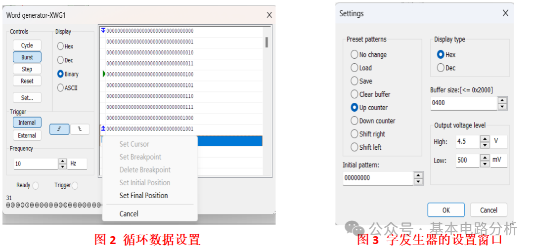
(5)Output data editing method. Each line of data in the display area can be manually modified, and data sequences can also be generated automatically (to be set in “Set..”). Click the left mouse button on the leftmost side of each line of data in the display area, a menu will pop up as shown in Figure 2, where you can set a certain line of data as initial Position(initial position)、Final Position(final position)、Breakpoint(breakpoint), etc., to set the starting and ending values for a group of loop data. After setting, the leftmost side of the starting data will have ablue down arrow mark, and the left side of the final value data will have ablue up arrow mark, while thegreen right arrow mark indicates the current output data.
(6)set…(set)
Click the left mouse button on the “set…” button on the operation panel, a settings window will pop up as shown in Figure 3.Preset Patterns(current mode): various modes can be selected.
No change(no change): regular output data;Load(load): data obtained from other files uploaded;Save(save): saves the current data to a file;Clear buffer(clear buffer): clears the current display area data (all reset to 0);Up counter(up counter): the system automatically generates display area data according to the up counting rule;Down counter(down counter): the system automatically generates display area data according to the down counting rule;Shift right(shift right): data shifts right;Shift left(shift left): data shifts left.
Display type(display type): can chooseHex(hexadecimal)、Dec(decimal) display.Buffer size(buffer size): can set the buffer size.Output voltage level(output voltage level): set the values of high and low output voltage levels,Initial pattern(initial pattern): default settings are sufficient.
2. Examples of Word Generator Applications
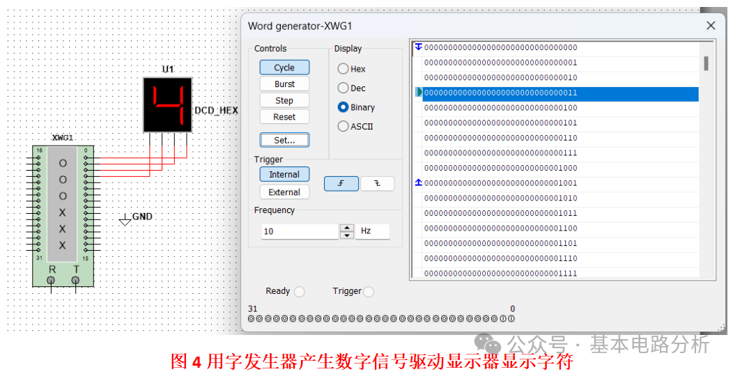
Place 1 word generator XWG1 and 1 seven-segment display U1 in the Multisim workspace, and connect them as shown in Figure 4. Set the word generator as shown in Figures 2 and 3, which automatically generates binary data according to the up counting rule, setting 0000 (only the low 4 bits) as the initial value, 1001 as the final value, meaning the binary data will loop between 0000-1001. Start the simulation, and you can observe that the display U1 shows data cycling between 0-9.