(Thanks to everyone for your likes and appreciation. If this article resonates with you, please “like” and “recommend”, thank you all!)
Article Overview
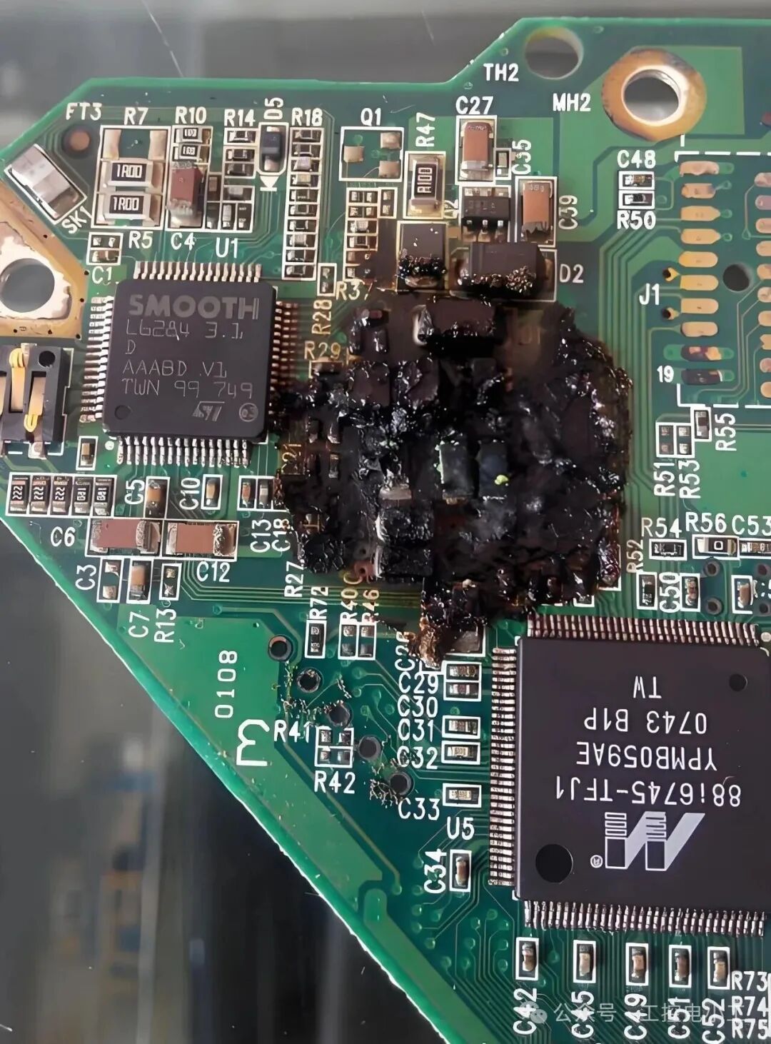
A few days ago, while debugging equipment, the CPU module of a running S7-1200 PLC suddenly crashed. After powering it back on, it reported an error, and the SF light remained on, completely “dead”. Upon inspection, the filter capacitor in the power supply section had exploded. After ruling out power and load issues, the final cause was lamentable—incorrect grounding! For the safety of your equipment, I have summarized common grounding mistakes in PLCs. If you have ever been unclear about grounding issues, please make sure to read this carefully.
1. Can Poor Grounding Burn Out the CPU?
Many people think, “Ground wire, just connect it anywhere, as long as it’s there, the equipment will run.” This is the biggest misconception! The core purposes of PLC grounding are twofold:
-
Safety Protection: Prevent electric shock accidents caused by leakage from the equipment casing.
-
Signal Reference and Interference Resistance: Provide a stable, clean “0 potential” reference point for the entire control system, suppressing electromagnetic interference.
The Fatal Consequences of Incorrect Grounding: When the grounding system is chaotic or ineffective, the ground cannot serve as a reliable “0 potential” reference. A “potential difference” (ground voltage drift) can occur between different devices, or even between different modules within the same cabinet.
This potential difference can create ground loops.
This current does not flow through your load but quietly and continuously flows through the shielding layer of communication cables, the common terminal (M) of the PLC’s 24V power supply, and even the IO lines.
The power circuit of the CPU module is designed with filter capacitors at the input to filter out interference (usually connected between the DC power L+/M and the protective ground PE). Ground loops can cause these capacitors to operate under overload for extended periods, leading to overheating and aging, ultimately resulting in capacitor breakdown or explosion, directly burning out the CPU’s power section!
This process is slow and covert, until one day it suddenly erupts.
2. The Three Most Common “Deadly” Grounding Methods on Site
Below are the most frequently encountered grounding mistakes I have found during on-site troubleshooting. Please check each one:
Error One: 【Series Grounding (Daisy Chain)】
-
Phenomenon: The PE wire of one device is connected to the grounding busbar of the electrical cabinet, then the PE wire of the second device is connected to the grounding screw of the first device, and so on.
-
Hazard: Ground loops will flow along this wire, and interference will be amplified step by step. If the first connection point becomes loose or corroded, all subsequent devices will lose effective safety protection, and the reference potential will be extremely chaotic.
Error Two: 【Poor Dual-End Grounding of Shielding Layers】
-
Phenomenon: The shielding layers of communication cables such as Profibus-DP and Ethernet are grounded at both the PLC end and the remote station end, but there is a potential difference at the grounding points or the grounding resistance is too high.
-
Hazard: This is equivalent to artificially building a “perfect” bridge for ground loops. Huge ground currents will flow in the shielding layer, which not only fails to provide shielding but also introduces strong interference, leading to communication interruptions or even damaging the CPU through the communication port.
Error Three: 【Floating or Poorly Connected Ground Wire】
-
Phenomenon: The ground wire is connected to a painted cabinet (without scraping the paint), or the terminal is poorly crimped, or the screws are not tightened.
-
Hazard: This is more dangerous than not grounding at all! Because it gives you the false sense of security that it is “grounded”. This high-impedance grounding point can act as an antenna, collecting various interferences from the environment and directly injecting them into the control system, causing the PLC to crash inexplicably or IO points to malfunction.
3. How Senior Engineers Teach You to Ground Correctly
Correct grounding is a “system engineering” task. Please remember the following golden rules:
-
Single Point Grounding Principle:
-
Install a sufficiently thick (recommended ≥25mm²) copper grounding busbar inside the electrical cabinet.
-
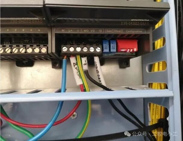
All devices that need grounding inside the cabinet (PLC, frequency converters, switch power supplies, instruments, etc.) should be connected directly to this grounding busbar using a separate, as short as possible, and sufficiently thick (≥2.5mm²) yellow-green wire. This is “star grounding”, the most effective way to avoid ground loops.
Shielding Layer Treatment Principle:
-
Single-end Grounding! Single-end Grounding! Single-end Grounding! (Important things are said three times)
-
The shielding layer of communication cables should be reliably grounded at the control cabinet end (PLC end), while the other end (sensor, remote station end) should be insulated with tape to keep it “floating”. This cuts off the path for ground loops.
Ensure Grounding Effectiveness:
-
The grounding busbar of the electrical cabinet must be connected directly to the factory’s main grounding electrode using sufficiently thick cables (≥16mm²). In cases where grounding resistance is required, use a grounding resistance tester to measure and ensure the resistance is less than 1Ω (or follow local regulations).
4. Urgent Self-Check List
If you are currently on-site or in the machine room, please check immediately:
-
Is the PLC’s PE terminal wire independently connected to the grounding busbar?
-
Is the shielding layer of the communication line grounded only at one end?
-
Are all grounding connection points secure, free of corrosion, and well-contacted?
-
Does the entire grounding busbar of the electrical cabinet ultimately lead to the ground?
Conclusion: Grounding is the most fundamental yet easily overlooked aspect of electrical engineering. It may not be as creative as programming, but it is the cornerstone of stable system operation. A standardized grounding operation costs very little but can save you tens of thousands in economic losses and immeasurable production downtime risks.
What grounding issues have you encountered on-site that led to failures? Feel free to share your experiences and lessons in the comments section so we can all avoid pitfalls together!
1
END
1
Previous Reviews
Practical Case: Two S7-1200 PLCs Achieving PROFINET Communication, Detailed Steps with Complete Programs, Follow the Steps to Achieve ItPractical Case | S7-1200 Loop Color Light Control, Complete Source Program Included, You Can Replicate It After Reading!Essential Skills for Senior Electricians: Siemens S7-1200 PLC Controlled Automatic DoorEssential Skills for Senior Electricians: Siemens S7-1200 PLC Controlled Traffic Light at IntersectionEssential Skills for Senior Electricians: Siemens S7-1200 PLC Controlled Automatic Assembly LineEssential Skills for Senior Electricians: Siemens S7-1200 PLC Controlled Automatic Mail Sorting Machine
If you enjoy the articles from Industrial Control Electrician, please click on the business card to follow me! I will continue to share technical insights about PLCs and industrial robots!