Circuit board materials are mainly divided into FPC flexible boards, FR-4, aluminum substrates, copper substrates (further divided into standard copper substrates and thermoelectric separation copper substrates), and ceramic substrates. This article aims to analyze the design considerations of each type of board material from the perspective of power design, summarized into the following three points:
1. Thermal Resistance
① FPC flexible boards are limited by the thermal resistance of the polyimide (PI) substrate and adhesive, with standard materials generally ensuring at least 100°C, while using heat-resistant enhanced materials can reach up to 150°C.
② FR-4 is composed of glass fiber cloth and epoxy resin. It is measured using a specific parameter Tg (glass transition temperature), with main types being TG130, TG150, and TG170. The actual usable temperature of the circuit board needs to be derated by about 40°C based on experience, so currently, the market mainly uses the latter two types.
③ Aluminum and copper substrates are mainly limited by the intermediate insulating layer material, which is typically a high polymer, usually restricting the long-term operating temperature to 140-150°C.
④ Ceramic substrates are primarily used for packaging power modules, and since they are inherently insulating, they can be said to have no upper temperature limit; the actual application temperature limit is constrained by the semiconductor devices.
2. Insulation
① FPC flexible boards are mainly used for signal connections, with interlayer withstand voltage applications below 100V posing no risk. For voltages above 100V, evaluation must be based on material thickness, spacing, and manufacturer testing data.
② The division of layers in FR-4 is relatively complex, with varying thicknesses between layers, resulting in differences in voltage withstand capability. Generally, the withstand voltage capability follows: surface bottom layer > inner inner layer > outer adjacent inner layer. The thickness of the outer inner layer is typically configured at 0.2-0.3mm, with a theoretical dielectric strength of 30kV/mm, thus the theoretical insulation capability of the outer inner layer is around 6kV, while the actual application insulation capability can generally ensure about 1kV.
③ Aluminum and copper substrates are also limited by insulating materials, but this voltage withstand capability can be selected, with a common choice being 2kV.
④ Ceramic substrates can reach 10-25kV/mm.
3. Thermal Conductivity
① FPC flexible boards are not involved;
② The empirical thermal conductivity coefficient of FR-4 is estimated to be 0.3W/mK;
③ The empirical thermal conductivity coefficient of aluminum substrates is estimated to be 1W/mK;
④ The empirical thermal conductivity coefficient of copper substrates is estimated to be 2W/mK;
⑤ The empirical thermal conductivity coefficient of thermoelectric separation copper substrates is estimated to be 380W/mK;
The main differences between copper substrates and thermoelectric separation copper substrates are as follows:
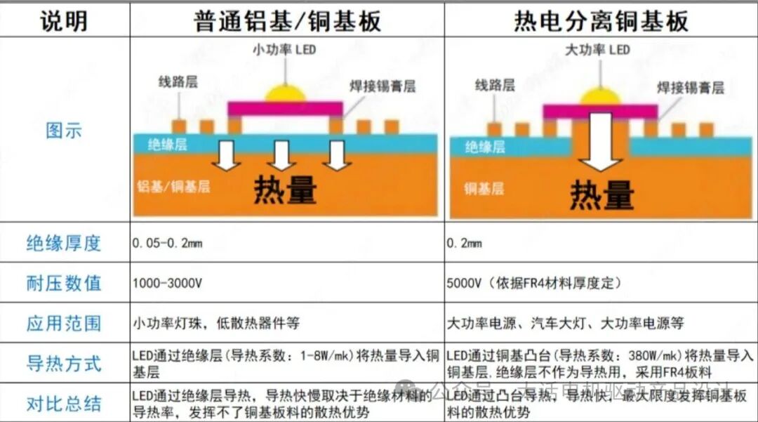 Figure 1 Image source: Jialichuang