1. Introduction to Frequency Counters
A frequency counter is an electronic instrument used to measure the frequency of periodic signals. In the STM32 microcontroller, we can utilize the input capture feature to achieve frequency measurement. The basic principle is to calculate the frequency by capturing the time interval between two consecutive rising (or falling) edges.
2. Hardware Configuration
1. STM32CubeMX Configuration
-
Select MCU: STM32F401CC
-
Clock Configuration: Configure the system clock according to requirements (it is recommended to use an external crystal oscillator for more accurate timing)
-
Timer Configuration:
-
Configure the input capture mode for each timer (TIM1, TIM2)
-
Select one channel for input capture for each timer (e.g., TIM1_CH1, TIM1_CH4, TIM2_CH1)
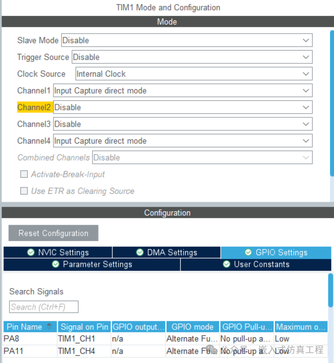
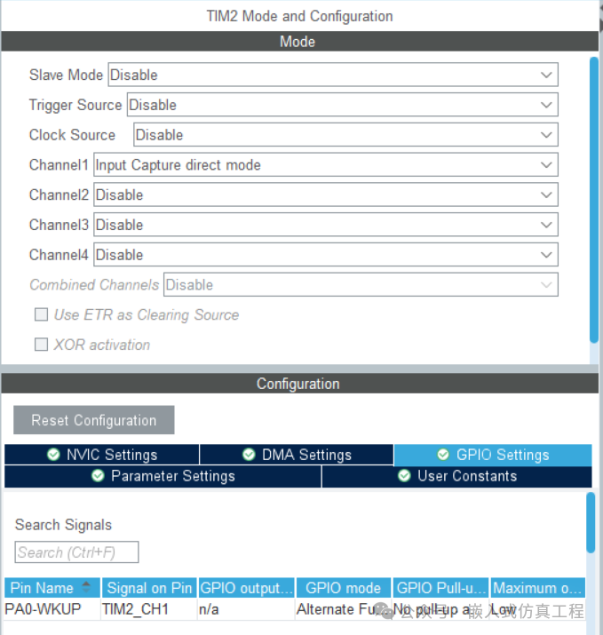
-
Configure the timer prescaler and period value
GPIO Configuration: Set the corresponding pins to input mode
LCD Configuration: Configure the parallel connection to the LGM12641BS1R screen
3. Generate IAR Project
After completing the configuration, with IAR version IAR FOR ARM 9.30, generate the IAR project and open it.
3. Software Implementation
Write application code and compile to generate a HEX file.
int main(void)
{
/* USER CODE BEGIN 1 */
/* USER CODE END 1 */
/* MCU Configuration——————————————————–*/
/* Reset of all peripherals, Initializes the Flash interface and the Systick. */
HAL_Init();
/* USER CODE BEGIN Init */
/* USER CODE END Init */
/* Configure the system clock */
SystemClock_Config();
/* USER CODE BEGIN SysInit */
/* USER CODE END SysInit */
/* Initialize all configured peripherals */
MX_GPIO_Init();
MX_TIM1_Init();
MX_TIM2_Init();
/* USER CODE BEGIN 2 */
Frec_init(&FREC1);
Frec_init(&FREC2);
Frec_init(&FREC3);
GLCD_Setup();
GLCD_Clear();
/* USER CODE END 2 */
/* Infinite loop */
/* USER CODE BEGIN WHILE */
while (1)
{
//GLCD_Clear();
GLCD_Clear();
if (FREC1.frec_leida==0) frecuencia1=0;
else
frecuencia1=FREC1.frec_muestreo/FREC1.frec_leida;
//set the read value to zero for another reading
FREC1.frec_leida=0;
//clear the used frequencies;
sprintf(texto,”Freq1=%.1fHz”,frecuencia1);
GLCD_SetFont(Font_11x13, 11, 13, mode);
GLCD_GotoXY(0, 1);
GLCD_PrintString_P(texto);
if (FREC2.frec_leida==0)
frecuencia2=0;
else
frecuencia2=FREC2.frec_muestreo/FREC2.frec_leida;
//set the read value to zero for another reading
FREC2.frec_leida=0;
//clear the used frequencies;
sprintf(texto,”Freq2=%.1fHz”,frecuencia2);
GLCD_SetFont(Font_11x13, 11, 13, mode);
GLCD_GotoXY(0, 22);
GLCD_PrintString_P(texto);
if (FREC3.frec_leida==0)
frecuencia3=0;
else
frecuencia3=FREC3.frec_muestreo/FREC3.frec_leida;
//set the read value to zero for another reading
FREC3.frec_leida=0;
//clear the used frequencies;
sprintf(texto,”Freq3=%.1fHz”,frecuencia3);
GLCD_SetFont(Font_11x13, 11, 13, mode);
GLCD_GotoXY(0, 43);
GLCD_PrintString_P(texto); //Print text #3
GLCD_Render();
//HAL_Delay(100);
/* USER CODE END WHILE */
/* USER CODE BEGIN 3 */
}
/* USER CODE END 3 */
}
4. Proteus Simulation
-
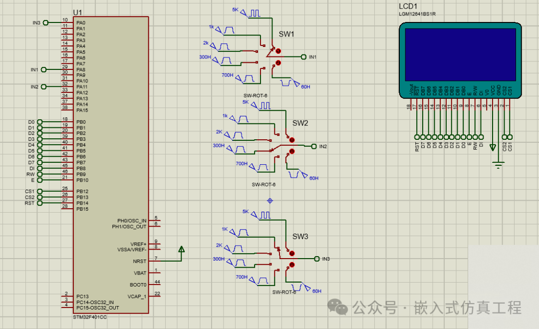
Create Proteus Project:
-
Add STM32F401CC MCU
-
Add LGM12641BS1R LCD module
-
Add 3 rotary switches, connecting different signals, to select the signal source to be measured
Configure Signal Sources:
-
Set square wave signals of different frequencies (e.g., 1kHz, 2kHz, 5kHz)
-
Connect to the corresponding input capture pins of the STM32
-
Import Program:
-
Import the hex file generated by IAR into the STM32 in Proteus
-
Set the correct clock frequency
Run Simulation:
-
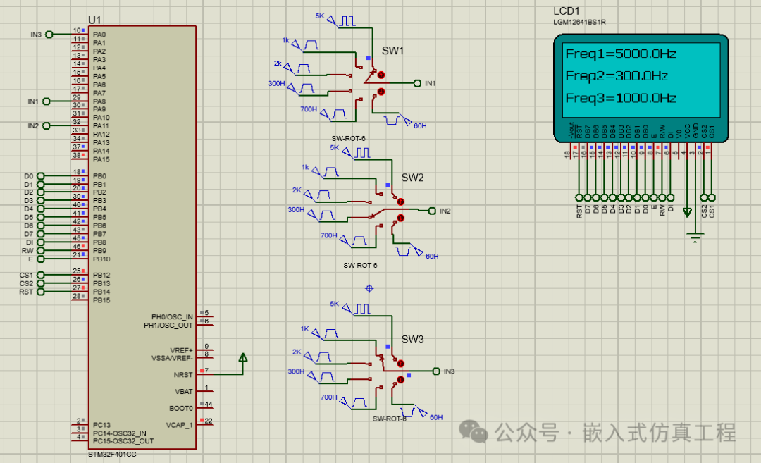
Observe whether the LCD correctly displays the frequencies of the three signals
-
You can adjust the signal source frequency to verify measurement accuracy
5. Precautions
-
Measurement Range:
-
High-frequency signals: Use timer overflow interrupts combined with capture values for calculation
-
Low-frequency signals: Can use external interrupts combined with timer counting
Accuracy Optimization:
-
Use a higher precision clock source
-
Add software filtering algorithms
-
Take multiple measurements and average the values
LCD Driver:
-
Ensure that the driver functions for the LGM12641BS1R are correctly implemented
-
Configure the correct interface based on the actual connection method (SPI/I2C)
Proteus Limitations:
-
The STM32 simulation in Proteus may not be completely accurate
-
Some peripheral behaviors may differ from actual hardware
By following the above steps, you can implement a three-channel frequency counter based on STM32 and perform simulation verification in Proteus. Adjustments may be needed for actual hardware implementation based on specific conditions.
Welcome to follow (operation reference article: Send a message to the public account), click the blue text at the top “Embedded Simulation Project” or long press to recognize the QR code to follow
Reply in the public account
3216
After receiving, it will automatically send the link to this IAR project