What is Arduino
Arduino is a convenient, flexible, and open-source microcontroller hardware and software platform, primarily used for electronic projects and prototyping. It is based on simple microcontroller boards and an integrated development environment (IDE), allowing both individuals and professionals to easily create interactive electronic objects using electronic components.
The core features of Arduino include:
- Open-source hardware: Circuit diagrams and PCB design files are fully open, allowing users to modify and replicate them.
- Simplified development: The Arduino IDE, based on C/C++, abstracts the underlying complex configurations, enabling beginners to get started quickly.
- Rich ecosystem: Compatible with tens of thousands of sensor and actuator modules, with extensive community resources (tutorials, projects).
- Cross-platform: The IDE can run on the three major operating systems: Windows, Mac OS, and Linux.
- Simple and clear: Developed based on the Processing IDE, it is friendly for beginners.
Arduino was first released in 2010, and the name “Uno” means “one” in Italian, symbolizing its positioning as “the first board for beginners.” The mainstream version is the Arduino Uno R3 (released in 2012), although there is a newer R4 version (released in 2023), the R3 remains the preferred choice for beginners due to its cost-effectiveness and mature ecosystem.
Performance and Parameters of Arduino UNO
Core Parameters
| Parameter | Specification | Description |
|---|---|---|
| Microcontroller | ATmega328P-PU (8-bit AVR microcontroller) | The “brain” of the development board |
| Operating Frequency | 16MHz | The clock frequency determines the computation speed |
| Flash Memory | 32KB (31.5KB usable) | Stores user-written programs |
| SRAM | 2KB | Temporarily stores variables and data (limited capacity) |
| EEPROM | 1KB | Retains data after power loss (e.g., calibration parameters) |
| Operating Voltage | 5V | The core operating voltage of the chip |
| Dimensions | 68.6mm × 53.4mm | Consistent with standard Arduino board layout |
Interfaces and Functions
-
Digital I/O Interfaces: 14 (numbered 0-13)
- 6 of which support PWM output (3, 5, 6, 9, 10, 11)
- 0 and 1 are serial communication interfaces (RX/TX)
-
Analog Input Interfaces: 6 (A0-A5)
- 10-bit resolution, can convert 0-5V voltage to a digital value of 0-1023
- A4 and A5 can also be used as I2C SDA and SCL
-
Peripheral Interfaces:
- SPI: 1
- I2C: 1
- UART: 1
-
Wireless Communication: Not supported (requires external modules)
- Wi-Fi: requires external module
- Bluetooth: requires external module
-
Power Supply Methods:
- USB interface: 5V power supply (for programming and communication)
- Power socket: supports external DC power input (recommended 7-12V, 6-20V limit)
- Voltage regulation: onboard 5V and 3.3V regulators
Application Scenarios
Arduino Uno, due to its ease of use, low cost, and rich community support, is particularly suitable for:
- Beginner learning
- Robot control
- Data collection and monitoring
- IoT projects (requires wireless modules)
- Interactive art installations
- Smart home prototype development
Comparison with Modern Development Boards
Compared to newer development boards like the ESP32-S3 UNO (which features a 240MHz dual-core processor), the Arduino UNO is weaker in performance, but its advantages include:
- Low cost, low entry barrier
- Rich community resources, abundant learning materials
- Stable and reliable, suitable for basic projects
- Simple code, beginner-friendly
As the “first board for beginners,” the Arduino UNO R3, with its simplicity, reliability, and low cost, remains the preferred development board for electronics enthusiasts and beginners, laying a solid foundation for learning embedded systems and the Internet of Things.
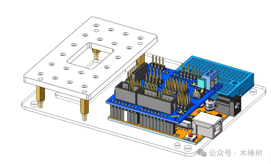
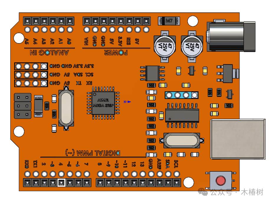
Detailed Description of Arduino UNO R3 Control Board
The Arduino UNO R3 control board is shown in the figure below
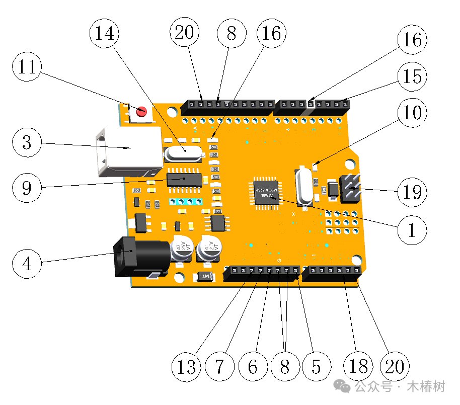
Core Brain: Microcontroller Unit (MCU)
The “brain” of the Arduino UNO R3 is ATmega328P-PU (shown in figure ①), an 8-bit AVR microcontroller. It acts like a mini-computer, responsible for processing all instructions and controlling external devices.
- Operating Frequency (shown in figure ②): 16MHz (slightly faster than older versions)
- Storage Capacity:
- 32KB Flash memory (31.5KB usable, for storing your programs)
- 2KB SRAM (temporary storage for variables, limited capacity, needs to be used wisely)
- 1KB EEPROM (retains data even when powered off, suitable for storing configuration parameters)
💡 Fun Fact: The “Uno” in UNO means “one” in Italian, symbolizing it as the first board for beginners, just like your “first” in the electronic world.
Power System: Energy Source
The “heart” of the Arduino UNO R3 needs energy, and there are several power supply methods:
- USB Interface (shown in figure ③): The most commonly used! Connect to a computer for power (5V) and to upload programs
- DC Power Socket (shown in figure ④): Suitable for situations where not connected to a computer, recommended input of 7-12V (below 7V may be unstable, above 12V may overheat)
- VIN Pin (shown in figure ⑤): Interface for directly connecting to an external power source (same function as the DC socket)
- Voltage Regulators:
- 5V regulator: provides stable 5V to the development board
- 3.3V regulator: provides 3.3V (maximum 50mA current, suitable for certain sensors)
Power Pins:
- 5V (shown in figure ⑥): stable 5V output (can power other components)
- 3.3V (shown in figure ⑦): stable 3.3V output (suitable for 3.3V devices)
- GND (shown in figure ⑧): ground, the reference point for all circuits
USB Interface (shown in figure ③): The Bridge to the Computer
- Type:
- USB-B type interface (same as used for printers)
- Function:
- Power supply (5V)
- Upload programs to the development board
- Serial communication (data exchange with the computer)
- Communication Chip (shown in figure ⑨): ATmega16U2 (responsible for USB to serial conversion)
- Indicator Lights (shown in figure 10):
- TX: lights up when sending data via serial
- RX: lights up when receiving data via serial
💡 Interestingly, the USB communication of the UNO is implemented through the ATmega16U2 chip, while the main control chip ATmega328P does not directly handle USB, making the circuit design simpler.
Reset Circuit
- Reset Button (shown in figure 11): The small button on the board, press it to restart
- Function: Allows Arduino to rerun the program
- Reset Pin (shown in figure 12): Can be connected to an external button for remote reset
Crystal Oscillator (shown in figure 14): The Clock Heartbeat
- 16MHz Ceramic Resonator: Provides a stable clock signal for the microcontroller
- Function: Ensures all operations occur at precise timing
📏 I/O Interfaces: Tentacles Connecting to the Outside World
📡 Digital I/O Pins (14, 0-13):
- Basic Function: Can read signals as input or control devices as output
- Special Functions:
- 0 and 1 (shown in figure 15): Serial communication (RX/TX)
- 3, 5, 6, 9, 10, 11 (shown in figure 16): Support PWM (Pulse Width Modulation), can simulate output
- 13: Connected to an LED (L indicator light, shown in figure 17)
💡 Digital signals have only two states: HIGH (about 5V) and LOW (0V), as simple as a switch.
Analog Input Pins (6, A0-A5, shown in figure 18):
- Function: Reads continuously varying voltage signals
- Resolution: 10-bit (0-1023, a total of 1024 values)
- Voltage Range: Default 0-5V
- Special Uses: A4 and A5 can also be used as I2C SDA and SCL
💡 Analog signals are like the readings of a thermometer, representing any temperature between 0-50 degrees, while digital signals can only be “hot” or “cold.”
Communication Interfaces: Channels to Communicate with the World
- SPI Interface (shown in figure 19): 10(SS), 11(MOSI), 12(MISO), 13(SCK)
- Used for high-speed data transmission, such as connecting to SD cards or displays
- I2C Interface (shown in figure 20): A4(SDA), A5(SCL)
- Two-wire communication, suitable for connecting multiple sensors
- UART Interface (shown in figure 15): 0(RX), 1(TX)
- Serial communication, used for data exchange with the computer
Other Important Components
- ICSP Interface (shown in figure 19): Directly connects to the microcontroller’s SPI interface, used for bootloader uploads and chip-level programming
- LED Indicator Lights:
- ON: Power indicator light (lights up when powered)
- TX: Serial transmission indicator light
- RX: Serial reception indicator light
- L: Programmable LED (connected to pin 13, can be programmed to control on/off)