1. What is Arduino IDE?
Arduino IDE is the official integrated development environment launched by Arduino. It is a cross-platform application software used for writing, compiling, and uploading code to Arduino development boards.
Its core function is to compile and link the simple C/C++ code you write (referred to as Sketch) into machine language that the Arduino microcontroller can understand, and upload it to the board via a USB cable.
2. Software Interface and Main Functional Areas
When you open Arduino IDE, you will see the following main sections:
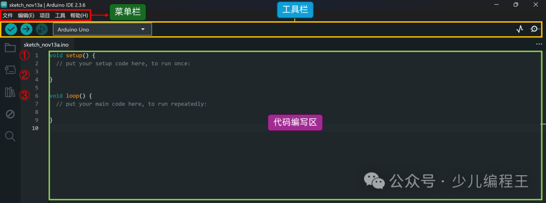
1. Menu Bar: Contains all main operations such as File, Edit, Sketch, Tools, Help, etc.
2. Toolbar:
-
Verify/Compile: Checks for syntax errors in the code and compiles it into machine code.
-
Upload: Uploads the compiled code to the connected Arduino board.
-
New: Creates a new Sketch file.
-
Open: Opens an existing Sketch file.
-
Save: Saves the current Sketch.
-
Serial Monitor: Opens the serial monitor window for communication with the Arduino board.
3. Code Editing Area: This is the main area where you write code. It supports syntax highlighting, simple code folding, and bracket matching.
4. Status Bar/Message Area: Displays information during the compilation and upload process, such as compilation progress, file size, error messages, etc.
3. Basic Program Structure
Each Arduino Sketch contains two essential functions:
// Initialization functionvoid setup() { Serial.begin(9600); // Start serial communication at 9600 baud rate}// Loop function, runs infinitely after setup()void loop() { // Place your main program code here, it will execute repeatedly Serial.println("Hello, World!"); // Send "Hello, World!" to the serial monitor}4. Lighting Up the Onboard LEDAlmost all Arduino development boards have an onboard LED marked as ‘L’, which is usually connected to digital pin 13. For convenience, the Arduino language also defines a constant for it as <span>LED_BUILTIN</span>.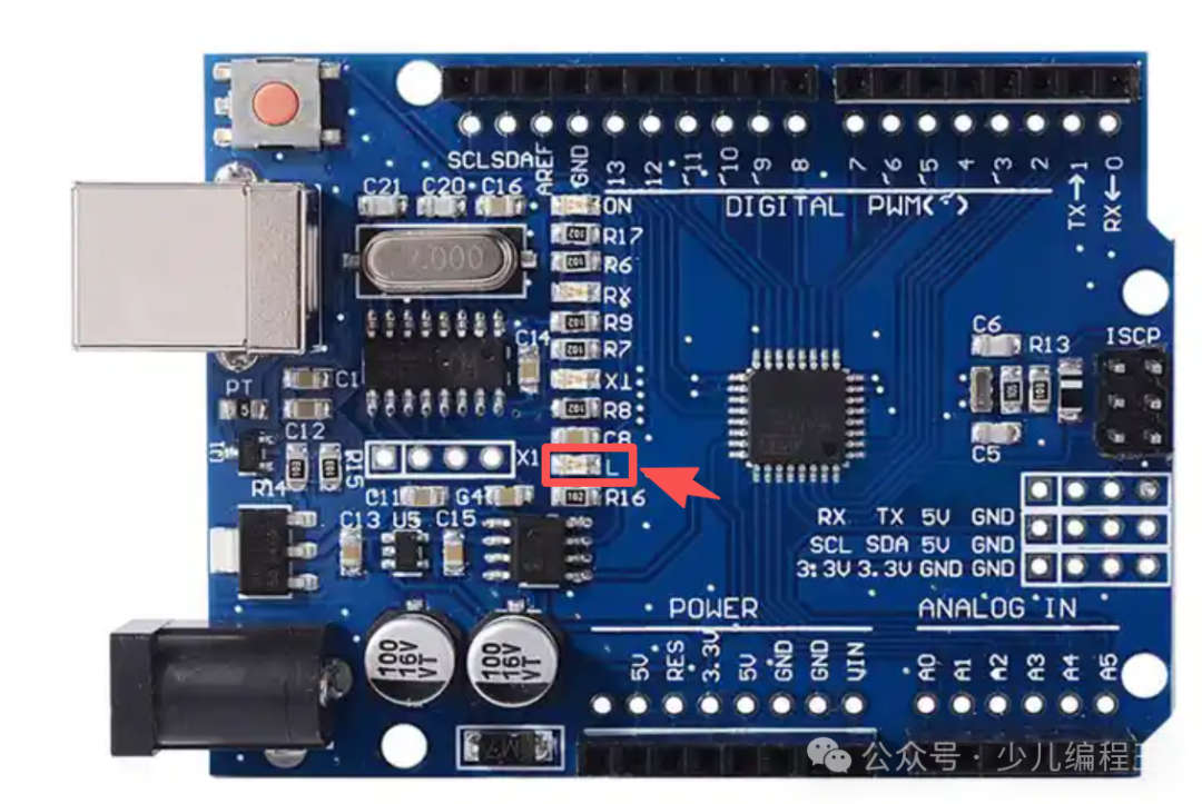 The program code is as follows:
/* Name: Onboard LED Blinking Program Function: Make the onboard LED connected to pin 13 blink at 1-second intervals*/void setup() { // Initialize LED pin as output mode // Because we want to output current to drive the LED pinMode(LED_BUILTIN, OUTPUT);}// Loop function, runs infinitely after setup()void loop() { digitalWrite(LED_BUILTIN, HIGH); // Output high level to LED pin (turn on LED) delay(1000); // Wait for 1000 milliseconds (1 second) digitalWrite(LED_BUILTIN, LOW); // Output low level to LED pin (turn off LED) delay(1000); // Wait for 1000 milliseconds (1 second)}Program Explanation:1.<span>setup()</span> Function:
void setup() { pinMode(LED_BUILTIN, OUTPUT);}-
<span>setup()</span>function runs once at the start of the program for initialization settings. -
<span>pinMode(LED_BUILTIN, OUTPUT);</span>This line of code sets the<span>LED_BUILTIN</span>pin to output mode. We want to control this pin to output current to light up the LED, rather than read external signals.
2.<span>loop()</span> Function:
void loop() { digitalWrite(LED_BUILTIN, HIGH); // Turn on LED delay(1000); // Wait for 1 second digitalWrite(LED_BUILTIN, LOW); // Turn off LED delay(1000); // Wait for 1 second}-
<span>loop()</span>function runs repeatedly after<span>setup()</span>has completed. -
<span>digitalWrite(LED_BUILTIN, HIGH);</span>: Outputs<span>HIGH</span>to the<span>LED_BUILTIN</span>pin (usually 5V or 3.3V). This creates a voltage difference across the LED, thus lighting up the LED. -
<span>delay(1000);</span>: Pauses the program for 1000 milliseconds (1 second). During this time, the LED remains lit. -
<span>digitalWrite(LED_BUILTIN, LOW);</span>: Outputs<span>LOW</span>to the<span>LED_BUILTIN</span>pin (0V). This eliminates the voltage difference across the LED, thus turning off the LED. -
<span>delay(1000);</span>: Again pauses the program for 1 second. During this time, the LED remains off. -
Then, the loop returns to the beginning, lighting up the LED again… and this continues, creating a blinking effect.
5. Steps to Operate
-
Connect Hardware: Connect your Arduino board (e.g., Uno) to the computer using a USB data cable.
-
Select Board and Port:
-
In Arduino IDE, click Tools > Board and select your board model (e.g., Arduino Uno).
-
Click Tools > Port and select the corresponding serial port (on Windows it is
<span>COMx</span>, on Mac it is<span>/dev/cu.usbmodem...</span>).
Upload Code:
-
Click the “Upload” button (right arrow) on the toolbar.
-
The IDE will first compile the code and then upload the program to the Arduino board via the USB cable.
Observe Results:
-
After a successful upload, you should immediately see the LED marked ‘L’ on the Arduino board start blinking steadily with a pattern of 1 second on, 1 second off.
6. Result Display