The oscilloscope is the most commonly used tool by hardware engineers,
which can be used for basic waveform testing, confirming whether related parameters meet requirements, and for diagnosing circuit anomalies;
it can also be used for eye diagram testing of high-speed signals, Ethernet port template testing, jitter analysis, etc.;
or for decoding commonly used serial signals such as I2C, SPI, CAN BUS, etc., helping to locate some issues.
When testing signals at different rates, it is important to select the correct oscilloscope.
The selection of an oscilloscope typically focuses on two parameters: bandwidth and sampling rate.
Oscilloscope Bandwidth
The bandwidth of an oscilloscope refers to the highest frequency it can effectively measure, usually defined as the frequency at which the amplitude of the input sine wave signal is attenuated to 0.707 times (-3dB). The larger the bandwidth, the wider the range of signal frequencies the oscilloscope can capture.
The standard for selecting oscilloscope bandwidth follows the 5x rule. To ensure that the oscilloscope can accurately capture the high-frequency components of the signal, it is generally recommended that the oscilloscope’s bandwidth be at least 5 times the frequency of the signal being measured. For example, if the signal frequency is 1MHz, the oscilloscope’s bandwidth should be at least 5MHz.
The relationship between signal rise time and bandwidth: bandwidth is inversely proportional to the rise time of the signal, which can usually be calculated using the formula Bandwidth × Rise Time = 0.35. This means that the larger the bandwidth, the shorter the rise time that can be accurately measured.
Oscilloscope Sampling Rate
The sampling rate of an oscilloscope refers to the number of samples collected per second, usually expressed in Samples per Second (S/s). The higher the sampling rate, the more signal details can be captured.
It is generally recommended to choose a sampling rate that is at least 2.5 times greater than the bandwidth, preferably more than 3 times.
Oscilloscope Probes
To accurately measure signal waveforms, the choice of oscilloscope is very important, but the choice of oscilloscope probes is also crucial, as the probe that connects the oscilloscope to the device under test is closely related to signal integrity, especially the length of the probe’s ground wire is also very critical.
Oscilloscope probes are divided into passive probes and active probes,
with passive probes further divided into high-impedance input probes and low-impedance resistive divider probes.
High-Impedance Passive Probes
High-impedance passive probes are inexpensive and are currently the most widely used probes.
The internal circuit is shown in the figure below:
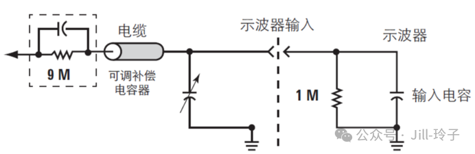
The probe resistance is 9MΩ, and the oscilloscope’s internal impedance can be set to 1 MΩ, so the amplitude of the waveform displayed by the oscilloscope is: Voscilloscope = Vprobe * (1 MΩ / (9 MΩ + 1 MΩ)), which means that the voltage displayed by the oscilloscope is one-tenth of the probe voltage, thus passive probes have a very wide dynamic range.
The following figure illustrates the passive high-impedance probe:
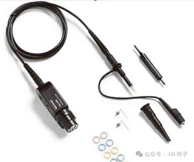 Low-Impedance Resistive Divider Probes Low-impedance resistive divider probes have input resistances of 450 ohms or 950 ohms, forming a 10:1 or 20:1 attenuation with the oscilloscope’s internal 50-ohm input, which is generally used for testing high-precision signals such as power ripple. Note that when using passive low-impedance probes, the oscilloscope’s internal impedance should be set to 50 ohms. The following figure illustrates the internal circuit of a low-impedance passive probe: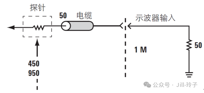
Active Single-Ended Probes
Active probes have low capacitive loading, so they are mainly used for measuring high-speed signals.
The following figure illustrates an active single-ended probe:
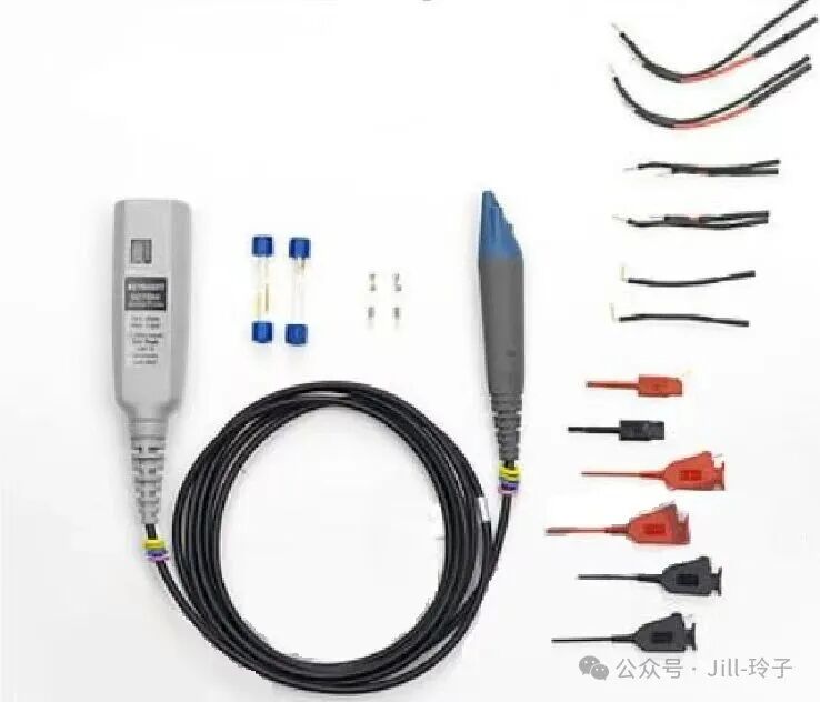
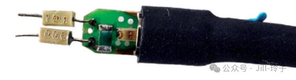
The following figure illustrates the front-end accessory of an active differential probe, which is generally soldered to the differential signal that needs to be tested during use.
Calibration of Passive High-Impedance Probes
If a passive high-impedance probe has not been used for a long time, it is best to calibrate it before use.
The following explains how to calibrate a passive probe.
As shown in the figure below, passive high-impedance probes all have an adjustable capacitor knob.
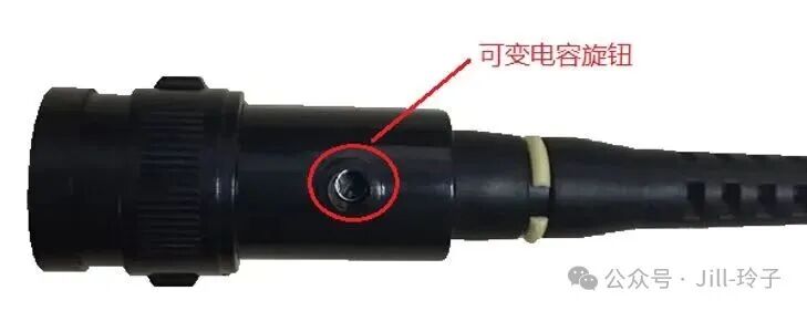
Calibration of the probe requires adjusting this variable capacitor knob with a screwdriver.
It is important to note that it is best to use the plastic tool that comes with the oscilloscope probe packaging to adjust the knob, rather than a metal screwdriver, because the variable capacitor itself has a small capacitance value, and using a metal screwdriver will change its capacitance value. The waveform that was originally adjusted well may become poor once the screwdriver is removed.
Calibration Process:
Oscilloscopes generally output a 1KHz, 5V (or lower) square wave signal, which is used for probe compensation calibration. This signal is commonly indicated by a square wave symbol with a ground symbol.
We can use this square wave signal as the signal source.
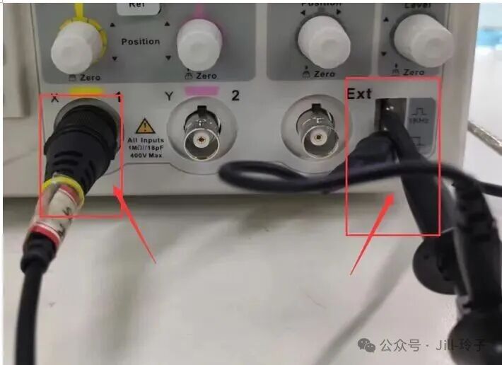
As shown in the figure below, connect the probe’s BNC to channel 1, and connect the other end of the probe to the square wave signal output port, ensuring proper grounding, and then start the calibration.
Specific calibration steps:
1): Connect the oscilloscope probe to the oscilloscope channel
2): Set the attenuation ratio of the oscilloscope probe to x10, and set the corresponding channel of the oscilloscope to x10
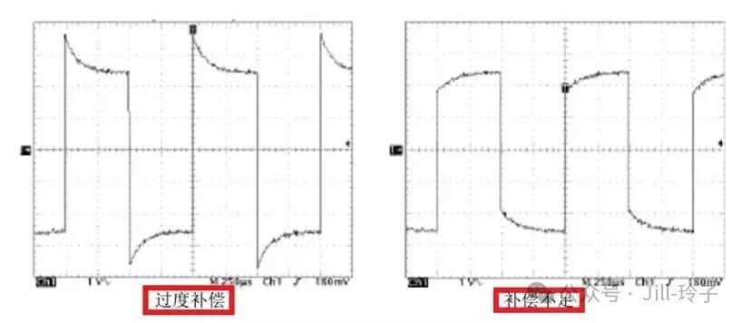
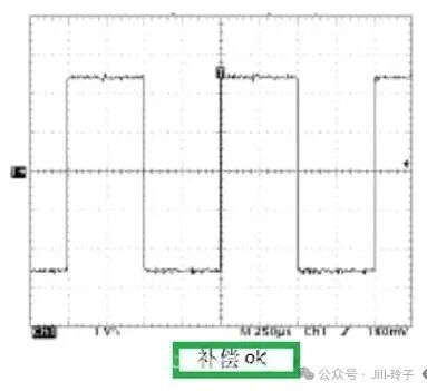
3): Measure the square wave generated by the oscilloscope, observe the waveform, and rotate the capacitor knob on the oscilloscope probe until the square wave waveform is optimal, with the judging standard shown in the figure below.
Once calibration is complete, we can start our measurements. 🙂