This blog post mainly provides a simple demonstration of the steps for implementing partial reconfiguration based on PCIe (MCAP). If there are any errors, please feel free to criticize and correct them. It is worth noting that partial reconfiguration based on PCIe can only be achieved on the UltraScale and UltraScale+ series chips. The specific series that can achieve which configuration methods are shown in the figure below:
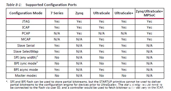
Figure 1
Essentially, whether it is JTAG, ICAP, MCAP, or other FPGA configuration methods, the goal is to configure the logic of the FPGA. MCAP is used to program the FPGA via PCIe, and the end result is the same as using JTAG for FPGA programming. However, using PCIe for FPGA programming offers better flexibility, which is essential in certain scenarios, such as in data acceleration deployments. In these cases, the FPGA acceleration card is located on the server side. After the service goes live, modifying the FPGA business logic using JTAG programming is quite inconvenient and highly impractical. Moreover, reprogramming the FPGA will cause the original FPGA PCIe device to be removed from the server, requiring a server reboot to re-enumerate the devices (currently, I have not found a method to re-enumerate devices after entering the system). For servers that are already online, rebooting the server after each switch of FPGA business logic is unacceptable. Therefore, using PCIe for partial reconfiguration of the FPGA is essential, allowing dynamic modification of a certain area of logic (business logic) while keeping the static logic of the FPGA (PCIe part and other non-business logic) functioning normally. This technology enables quick switching of business logic without rebooting the server.
This implementation is based on Xilinx’s VCU1525 acceleration card, which features an UltraScale+ FPGA (VU9P). From the above figure, we can see that UltraScale+ series FPGAs support MCAP configuration mode. Below is a simple example that demonstrates MCAP partial reconfiguration.
1. Create a new blank project.

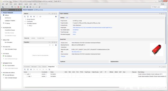
Figure 2
2. Since we are using the MCAP configuration method, which is integrated into the PCIe hard core, we need to instantiate a PCIe-related IP. Here we will use XDMA for this example (bare PCIe hard core can also be used). This example does not include relevant content for data DMA transfer using XDMA; it merely utilizes the MCAP functionality from XDMA. Currently, I also have a rather painful issue, which is how to integrate the host driver of XDMA with the MCAP driver. I feel quite lost regarding host driver development. If any experts understand this, we can discuss it.
3. In the Board option (this option is available only when selecting Xilinx official board during project creation), select as shown below.
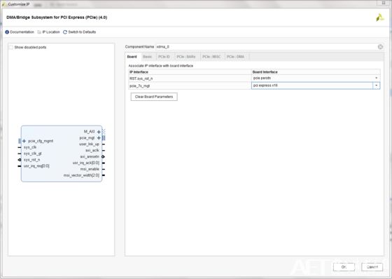
Figure 3
4. In the Basic option, set the Mode in the red box in the figure to Advanced.
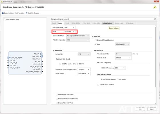
Figure 4
5. In the Basic option, at the bottom, select PR over PCIe in the Tandem Configuration or Partial Reconfiguration section.
Figure 5
6. In the PCIe ID option, set the Device ID to 8011 (since the drivers provided by Xilinx support 8011, 8038, 506F).
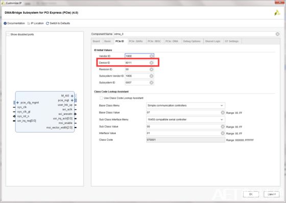
Figure 6
7. Keep other options as default and generate this IP.
Figure 7
8. For the convenience of testing and implementation, use the XDMA Example Design to modify the example. After synthesizing XDMA (remember to select OOC), open the Example Design of this IP and make modifications on this project.
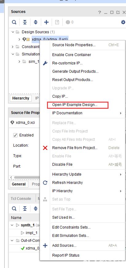
Figure 8
9. The Example Design is shown in the figure below.
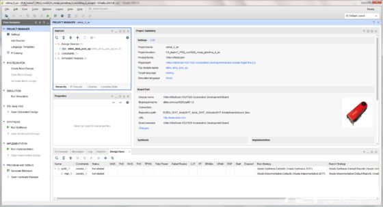
Figure 9
10. First, we will modify the XDC file and the top level of the project, mainly the LED pins and level constraints. In this example, we will implement two reconfigurable modules: one for controlling the LED light on the VCU1525 and the other for controlling the LED light off. This simple example illustrates the steps for implementing PR.
11. Modify the clock generation IP in the project; this step is not necessary but mainly specifies the input clock pin. If it is not an official board, constraints can be set in the XDC.
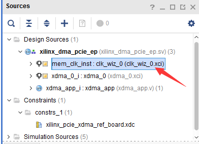
Figure 10
12. Create two modules: LED_RM_0 and LED_RM_1. LED_RM_0 is used to control the LED off, while LED_RM_1 is used to control the LED on. The logic of both modules is simple and is for demonstration purposes. The code logic is as follows.
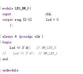
Figure 11
13. Instantiate one of the RM modules at the top level of the project.
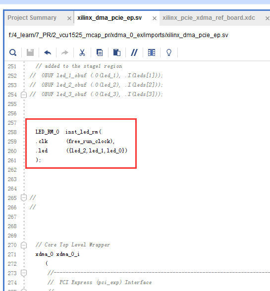
Figure 12
14. After completing the above steps, select Tools -> Enable Partial Reconfiguration… to convert the project into a PR-supported type. In the subsequent pop-up box, select Convert.
Figure 13
15. The project has now been successfully converted. Compared to before the conversion, there is now a Partial Reconfiguration Wizard option in the Flow Navigator’s PROJECT MANAGER.
Figure 14
16. Set the logic that we want to partially reconfigure, namely the LED_RM_x module, as shown in the figure below. Right-click on LED_RM_0 and select Create Partition Definition…
Figure 15
17. In the pop-up window, specify a name for the partition. Here, we set it as LED_RM and click OK.
Figure 16
18. After completing the previous step, the LED_RM_0 module will change to a yellow diamond symbol, as shown in the figure below.
Figure 17
19. Open the Partial Reconfiguration wizard.
Figure 18
20. In the Edit Reconfiguration Modules interface, click the “+” sign to add LED_RM_1, indicating that there are two reconfigurable modules. After adding, it will look like the figure below, showing LED_RM_0 and LED_RM_1 in the LED_RM partition definition list.
Figure 19
21. In the Editing Configurations interface, select automatically create configurations and modify the Configuration Name, as shown in the figure below.
Figure 20
22. In the Edit Configuration Runs interface, select automatically create configurations.
Figure 21
23. Finally, click Finish to complete the settings of the partial reconfiguration wizard, then click Run Synthesis to synthesize the design.
Figure 22
24. After synthesis is complete, open the synthesized design.
Figure 23
25. In the Floorplanning interface, right-click on LED_RM_0, select Floorplanning -> Draw Pblock to define the reconfiguration area for the RM module.
Figure 24
26. After assigning the reconfiguration area, save the corresponding constraints to the XDC file, and then perform a DRC check to verify that the assigned area meets the requirements.
Figure 25
27. After the DRC check is completed without issues, click Generate Bitstream.
Figure 26
28. Thus, the partial reconfiguration project is completed. In the generated files, there will be two imp folders in the project directory, containing the static logic and their respective reconfigurable logic. We will first program the static logic into the FPGA, after which we can dynamically configure the logic via PCIe. Detailed explanations regarding the MCAP driver for the host can be found in the Xilinx Answer 64761 document regarding UltraScale Devices.
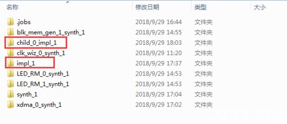
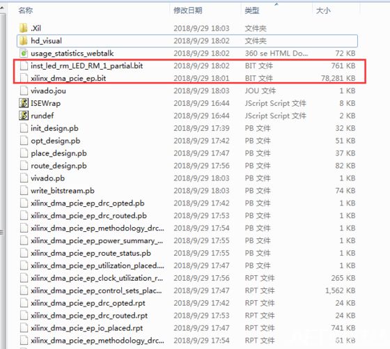
Figure 28
Recruitment Information