
1. Networking Requirements
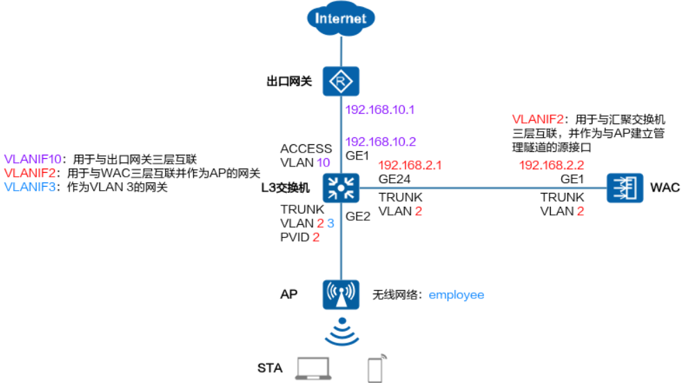
The enterprise has an export gateway<span>AR</span>, a core switch (<span>L3</span>),<span>WAC</span>, and<span>AP</span> devices, and hopes to deploy a wireless network to provide employees with wireless internet access.
The specific requirements are described in the table below:
| Requirement | Specific Description |
|---|---|
<span>WAC</span> Networking Method |
Side-hanging Layer 2 Networking |
| Business Data Forwarding Method | Direct Forwarding (default method) |
<span>DHCP</span> Deployment Method |
The core switch acts as the<span>DHCP</span> server to assign<span>IP</span> addresses to<span>AP</span> and<span>STA</span> |
<span>AP</span> Management |
<span>VLAN: 2</span> Subnet: <span>192.168.2.0/24</span> Gateway: The<span>VLANIF2</span> interface on the core switch<span>IP</span> |
| Wireless Service | <span>VLAN: 3</span><span>SSID: employee</span> Password: Superman_20240930 Subnet: 192.168.3.0/24 Gateway: The<span>VLANIF3</span> interface on the core switch<span>IP</span> |
<span>WAC</span> Source Interface for Management Tunnel with<span>AP</span> |
<span>WAC</span> on<span>VLANIF2</span> |
<span>WAC</span> Interface for Layer 3 Interconnection with Core Switch |
<span>VLANIF2</span> |
| Core Switch Interface for Layer 3 Interconnection with Export Gateway | <span>VLANIF10</span> |
The networking diagram is as follows:
2. Configuration Steps
2.1 Configure the Core Switch
1) Configure Management VLAN and Business VLAN
<L3> system-view  // Enter system view
[L3] vlan batch 2 3  // Create planned management VLAN and business VLAN
[L3] interface ge 0/0/2  // Enter the physical interface connected to AP
[L3-GE0/0/2] port link-type trunk  // Set the link type of the interface to trunk
[L3-GE0/0/2] port trunk pvid vlan 2  // Specify the default VLAN of the interface as the management VLAN of AP
[L3-GE0/0/2] port trunk allow-pass vlan  2 3  // Allow management VLAN and business VLAN to pass
[L3-GE0/0/2] quit
[L3] interface ge 0/0/24  // Enter the physical interface connected to WAC
[L3-GE0/0/24] port link-type trunk  // Set the link type of the interface to trunk
[L3-GE0/0/24] port trunk allow-pass vlan 2  // Allow management VLAN to pass
[L3-GE0/0/24] quit
2) Configure DHCP Server
Here, configure the<span>DHCP</span> server to assign<span>IP</span> addresses to<span>AP</span> and<span>STA</span>:
[L3] dhcp enable  // Enable DHCP service function
[L3] interface vlanif 2  // Create management VLAN interface
[L3-Vlanif2] ip address 192.168.2.1 255.255.255.0  // Configure planned IP
[L3-Vlanif2] dhcp select interface  // Enable DHCP server function using interface address pool
[L3-Vlanif2] dhcp server excluded-ip-address 192.168.2.2  // Exclude the connected WAC address from the DHCP address pool
[L3-Vlanif2] quit
[L3] interface vlanif 3  // Create business VLAN interface
[L3-Vlanif3] ip address 192.168.3.1 255.255.255.0  // Configure planned IP
[L3-Vlanif3] dhcp select interface  // Enable DHCP server function using interface address pool
[L3-Vlanif3] dhcp server dns-list 223.5.5.5 223.6.6.6  // Configure DNS server addresses used by users when accessing the internet
[L3-Vlanif3] quit
3) Configure Layer 3 Interconnection with Export Gateway
[L3] vlan batch 10  // Create planned interconnection VLAN
[L3] interface ge 0/0/1  // Enter the physical interface connected to the export gateway
[L3-GE0/0/1] port link-type access  // Set the link type of the interface to access
[L3-GE0/0/1] port default vlan 10  // Specify the default VLAN of the interface as the interconnection VLAN
[L3-GE0/0/1] quit
[L3] interface vlanif 10  // Create interconnection VLAN interface
[L3-Vlanif10] ip address 192.168.10.2 255.255.255.0  // Configure planned IP
[L3-Vlanif10] quit
[L3] ip route-static 0.0.0.0 0.0.0.0 192.168.10.1  // Configure default route, next hop (192.168.10.1) is the interface IP on the interconnection device
[L3] return
2.2 Configure Wireless Network Controller WAC
2.2.1 Configure AP Online
# 1) Transparent Management<span>VLAN</span>
<WAC> system-view
[WAC] vlan batch 2  // Create planned management VLAN
[WAC] interface ge 0/0/1  // Enter the physical interface connected to the core switch
[WAC-GE0/0/1] port link-type trunk  // Set the link type of the interface to trunk
[WAC-GE0/0/1] port trunk allow-pass vlan 2  // Allow management VLAN to pass
[WAC-GE0/0/1] quit
# 2) Specify Source Interface for Establishing CAPWAP Tunnel with<span>AP</span>
[WAC] interface vlanif 2  // Create management VLAN interface
[WAC-Vlanif2] ip address 192.168.2.2 255.255.255.0  // Configure planned IP
[WAC-Vlanif2] quit
[WAC] capwap source interface vlanif 2  // Specify source interface as the management VLAN interface
Note:
When configuring the
<span>CAPWAP</span>source interface or source address, it will check whether security-related configurations exist, including<span>DTLS</span>encryption<span>PSK</span>, username and password for logging in to<span>AP</span>, and global offline management<span>VAP</span>access password, all of which must exist for successful configuration; otherwise, the user will be prompted to complete the relevant configurations first.
Set the DTLS PSK(contains 8-32 plain-text characters, or 128 or 148 cipher-text characters that must be a combination of at least two of the following: lowercase letters a to z, uppercase letters A to Z, digits, and special characters):   // Configure DTLS encrypted PSK
Confirm PSK:   // Repeat input of DTLS encrypted PSK, both inputs must match
Info: Deliver DTLS PSK to devices using CAPWAP connections. It may take a few minutes.
Set the user name for FIT APs(The value is a string of 4 to 31 characters, which can contain letters, underscores, and digits, and must start with a letter):admin   // Uniformly configure the login username for FIT APs
Set the password for FIT APs(plain-text password of 8-128 characters or cipher-text password of 128-268 characters that must be a combination of at least three of the following: lowercase letters a to z, uppercase letters A to Z, digits, and special characters):   // Uniformly configure the login password for FIT APs
Confirm password:   // Repeat input of FIT AP's login password, both inputs must match
Set the PSK of the global offline management VAP(plain-text password of 8-63 characters or cipher-text password of 128-188 characters that must be a combination of at least two of the following: lowercase letters a to z, uppercase letters A to Z, digits, and special characters):   // Configure the access password for global offline management VAP
Confirm PSK:   // Repeat input of global offline management VAP access password, both inputs must match
Warning: Ensure that the management VLAN and service VLAN are different. Otherwise, services may be interrupted.
Warning: Before an added device goes online for the first time, enable DTLS no-auth if it runs a version earlier than V200R021C00 or enable DTLS certificate-mandatory-match if it runs V200R021C00 or later.
[WAC] capwap dtls no-auth enable  // WAC defaults to enabling DTLS encryption for the CAPWAP control tunnel. When adding APs, if the AP fails to go online, it is necessary to first enable CAPWAP DTLS no-auth mode to allow the AP to go online to obtain security credentials. After the AP goes online, this function should be promptly disabled (undo capwap dtls no-auth enable) to prevent unauthorized APs from going online.
Warning: This operation allows for device access in non-DTLS encryption mode even when DTLS is enabled and brings security risks. After the device goes online for the first time, disable this function to prevent security risks. Continue? [Y/N]:y
# 3) Configure AP Authentication Mode
[WAC] wlan  // Enter WLAN view
[WAC-wlan] ap auth-mode no-auth  // Set AP authentication mode to no authentication
Note:
<span>AP</span>authentication mode is set to no authentication, as long as the<span>AP</span>accesses the network and communicates with<span>WAC</span>, it can automatically go online. There is no need to manually add<span>AP</span>or manually confirm the information of unverified<span>AP</span>, which simplifies the configuration process.However, this method has security risks, and it is necessary to ensure that the network environment is secure, with no unplanned
<span>AP</span>present in the network; otherwise, it is recommended that users use more secure<span>MAC</span>address authentication or<span>SN</span>authentication.
Note:<span>AP</span> After powering on, when executing the commanddisplay ap all to check the<span>AP</span> state field as<span>nor</span>, it indicates that the<span>AP</span> is online normally:
[WAC-wlan] display ap all
Total AP information:
nor  : normal          [1]
ExtraInfo : Extra information
P  : insufficient power supply
Total: 1
----------------------------------------------------------------------------------------------------
ID   MAC            Name   Group     IP              Type                  State STA Uptime      ExtraInfo
----------------------------------------------------------------------------------------------------
0    00e0-fc11-1111 area_1 default   192.168.2.208   AirEnginexxxx         nor   0   4H:49M:11S  -
----------------------------------------------------------------------------------------------------
2.2.2 Configure<span>WLAN</span> Services
# 1) Configure VAP Template (employee)
[WAC-wlan] quit
[WAC] vlan batch 3  // Create planned business VLAN
[WAC] wlan  // Enter WLAN view
[WAC-wlan] security-profile name employee  // Create a security template named "employee"
[WAC-wlan-sec-prof-employee] security wpa-wpa2 psk pass-phrase Superman_20240930 aes  // Set wireless password
[WAC-wlan-sec-prof-employee] quit
[WAC-wlan] ssid-profile name employee  // Create an SSID template named "employee"
[WAC-wlan-ssid-prof-employee] ssid employee  // Specify SSID as "employee"
[WAC-wlan-ssid-prof-employee] quit
[WAC-wlan] vap-profile name employee  // Create a VAP template named "employee"
[WAC-wlan-vap-prof-employee] security-profile employee  // Reference security template
[WAC-wlan-vap-prof-employee] ssid-profile employee  // Reference SSID template
[WAC-wlan-vap-prof-employee] service-vlan vlan-id 3  // Specify VAP's business VLAN
[WAC-wlan-vap-prof-employee] quit
2) Configure VAP (Reference VAP Template)
Note: Since no separate<span>AP</span> group was configured for the<span>AP</span>, it will automatically join the<span>default</span> AP group named<span>default</span>, so configuring the default<span>AP</span> group<span>default</span> to reference the<span>VAP</span> template is sufficient.
[WAC-wlan] ap-group name default
[WAC-wlan-ap-group-default] vap-profile employee wlan 1 radio all
[WAC-wlan-ap-group-default] quit
[WAC-wlan] quit
2.2.3 Configure Layer 3 Interconnection with Core Switch
[WAC] ip route-static 0.0.0.0 0.0.0.0 192.168.2.1  // Configure default route, next hop (192.168.2.1) is the interface IP on the interconnection device
[WAC] return
2.3 Configure Export Gateway AR
2.3.1 Configure AR’s LAN Side (Interconnection with Core Switch)
# 1) Configure Interconnection Interface IP
There are two cases for Layer 2 and Layer 3 interfaces:
If using a Layer 2 interface (assumed to be<span>GE1</span>) to connect to the core switch, it is necessary to create the corresponding<span>VLAN</span> interface for the VLAN to which the interface belongs and then configure the<span>IP</span>.
<AR> system-view
[AR] vlan batch 10  // Create planned interconnection VLAN
[AR] interface GE 0/0/1  // Enter the physical interface connected to the core switch
[AR-GE0/0/1] port link-type access  // Set the link type of the interface to access
[AR-GE0/0/1] port default vlan 10  // Specify the default VLAN of the interface as the interconnection VLAN
[AR-GE0/0/1] quit
[AR] interface vlanif 10  // Enter the interconnection VLAN interface
[AR-Vlanif10] ip address 192.168.10.1 255.255.255.0  // Configure planned IP
[AR-Vlanif10] quit
If using a Layer 3 interface (assumed to be<span>GE1</span>) to connect to the core switch, then the<span>IP</span> can be configured directly.
<AR> system-view
[AR] interface ge 0/0/1  // Enter the physical interface connected to the core switch
[AR-GE0/0/1] ip address 192.168.10.1 255.255.255.0  // Configure planned IP
[AR-GE0/0/1] quit
2) Configure Routing to Internal Network Segment
[AR] ip route-static 192.168.2.0 255.255.255.0 192.168.10.2  // Next hop (192.168.10.2) is the interface IP on the interconnection device
[AR] ip route-static 192.168.3.0 255.255.255.0 192.168.10.2
[AR] return
2.3.2 Configure AR’s External Network Side
The configuration of the external network side is not directly related to the internal network and needs to be configured according to the internet access method provided by the operator.
Click the card above to follow us👆
Reply with the corresponding number in the background to receive Huawei Network Engineer learning materials