 I2C Bus (
Inter-Integrated Circuit)is a two-wire serial bus developed by PHILIPS for connecting microcontrollers and their peripherals. It is a widely adopted bus standard in the field of microelectronics control. It is a special form of synchronous communication, characterized by fewer interfaces, simple control methods, fewer device packaging forms, and high communication rates.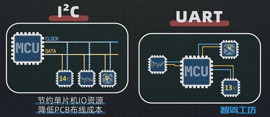
The I2C bus primarily addresses the issue of one-to-many communication for microcontrollers. By constructing a single information channel, it only requires two I/O ports and two wires to connect the chips on a circuit board, allowing for data transmission between them. Compared to UART communication, it can significantly save microcontroller I/O resources while reducing PCB wiring costs.
With so many devices sharing a single bus, it is necessary to adhere to certain communication rules.
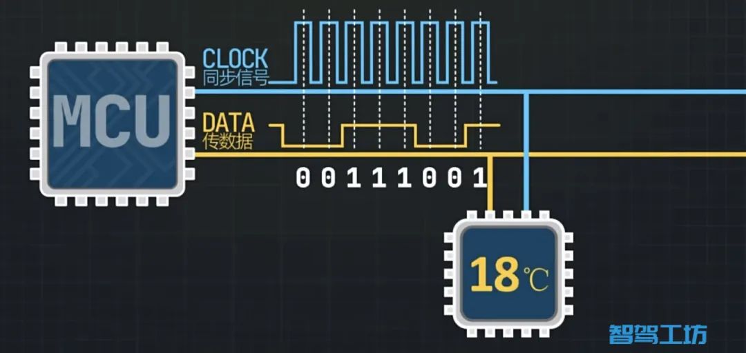
The I2C bus consists of two lines: the clock line and the data line, where the clock line is used to synchronize signals. The sender transmits data on the high level of the clock, and the receiver reads the data on the high level of the clock.
Now, the question arises: what happens if two devices on the bus want to send data at the same time? For example, if device A sends a 1 (high level) and device B sends a 0 (low level), what will be displayed on the data line? To clarify this issue, let’s first explain how chips output high and low levels.
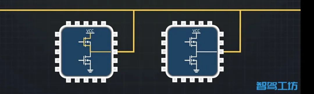
Typically, there are two MOSFETs inside the chip’s I/O port. When the upper MOSFET is turned on, it outputs a high level; when the lower MOSFET is turned on, it outputs a low level.
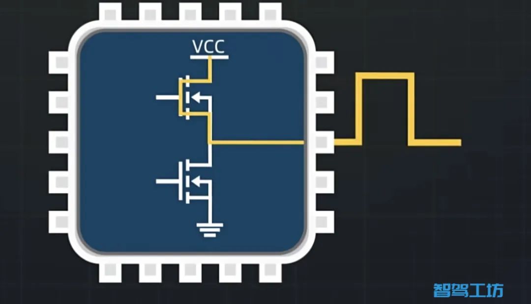
If both I/O ports are connected to the same bus, and the left one outputs a high level while the right one outputs a low level, the current will flow directly into the right chip, causing a short circuit and potentially damaging the chip.
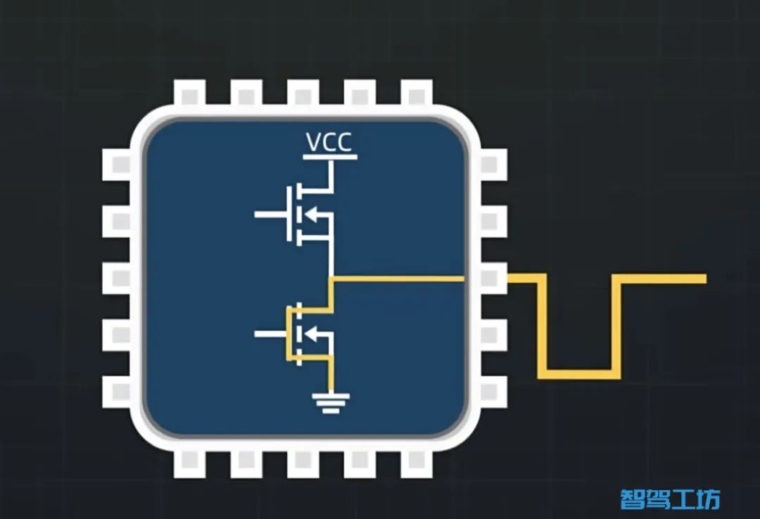
Therefore, the I2C bus has made some modifications to the device’s I/O ports by removing the upper MOSFET, thus avoiding the short circuit phenomenon.

This introduces another problem: devices can only output low levels and cannot output high levels. What should be done? This leads to the concept of pull-up resistors, which are added to the bus as shown in the diagram below.
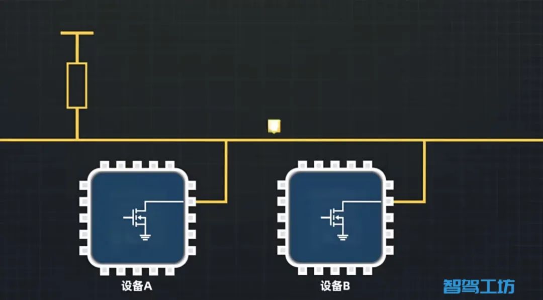
After adding the pull-up resistor, the bus defaults to a high level state. If a chip wants to output a low level, it turns on the MOSFET to pull the bus signal low. To output a high level, it simply needs to turn off the MOSFET, allowing the pull-up resistor to pull the bus to a high level state.
Consideration 🤔: What happens if two devices want to send signals simultaneously?
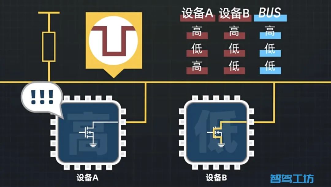
Suppose both devices want to output a high level; then both MOSFETs are turned off, and the bus remains in a high level state. If both devices output low levels, both MOSFETs are turned on, and the bus is in a low level state. If one device outputs a high level and the other outputs a low level, the bus will ultimately be in a low level state. This is essentially a matter of line and logic, and I will share more about logic circuits later. Therefore, the device that wants to output a high level does not actually output a high level on the bus; this is where software protocols come into play.