Introduction
When it comes to driver development, we must mention the bus; the bus is the bridge for data transmission between devices. Computers categorize buses into three types: data bus, address bus, and control bus, which are collectively referred to as the system bus. Generally, the system bus, internal bus, and external bus are known as the three major buses of a computer. Buses can be further classified into parallel/serial and full-duplex/half-duplex/simplex, which will be introduced in a separate chapter, summarizing and distinguishing these types of buses.
I2C Bus
The I2C bus is a two-wire (SDA/SCL), half-duplex, serial, multi-master interface standard that can connect multiple devices, featuring a bus arbitration mechanism. The I2C bus was developed by PHILIPS for connecting microcontrollers and their peripherals.
– Two Wires (SDA/SCL)
One data line (SDA) is used for data transmission; one clock line is used to generate timing. During data transmission, the I2C bus has three types of signals: start signal, stop signal, and acknowledgment signal.
1) Start Signal: When SCL is high, and SDA transitions from high to low, it indicates the start of data transmission.
2) Stop Signal: When SCL is high, and SDA transitions from low to high, it indicates the end of data transmission.
3) Acknowledgment Signal: After the receiver receives 8 bits of data, during the 9th clock cycle, it pulls SDA low to indicate that data reception is complete.
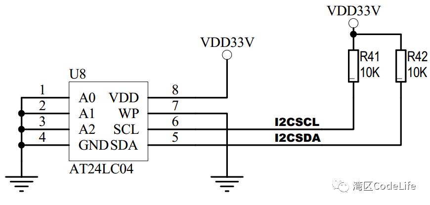
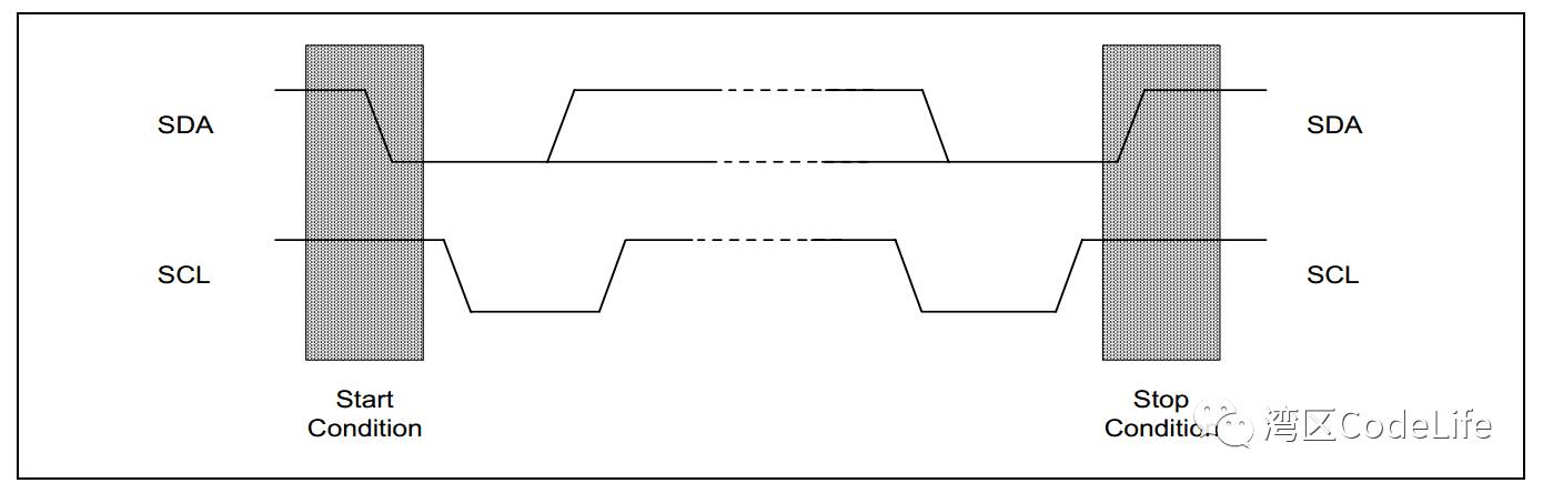
Most I2C devices, as shown in the figure, have pull-up resistors on the SDA and SCL lines, allowing both lines to maintain a high level in idle state; by changing the high and low levels on the two lines, the I2C state can be controlled. As seen in the timing diagram below, both SDA and SCL start at high level; when SCL is high and SDA transitions from high to low, a START signal is generated; after the stop signal is issued, both SDA and SCL return to the initial state, which is high level. The timing diagram also shows that when the START signal is sent, the master sends 8 bits of data, with the first 7 bits being the slave address and the 8th bit indicating the direction of transmission (0 for write operation, 1 for read operation). Since the address is 7 bits, the I2C bus can connect up to 128 devices.
Once the communication between the master and slave is established, data transmission begins. As shown in the figure, the data on SDA (0/1) changes only during the low level of SCL (see the red line in the figure), while the data on SDA remains stable during the high level of SCL (see the blue line in the figure). This is because data collection from the slave device occurs during the high level of SCL, requiring that the SDA data remains unchanged during the high level of SCL. After the 8 bits of data transmission (one bit per clock cycle), the master releases control of the SDA line; at this point, due to the pull-up resistor, the SDA line returns to high level. During the 9th clock cycle, the slave pulls the SDA line low; when the master detects that the SDA line is pulled low, it indicates that the slave has completed data reception.
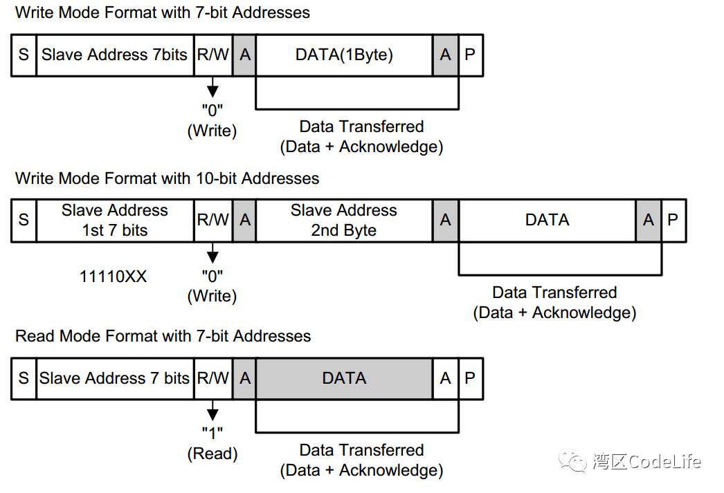
The following diagram shows the I2C bus timing of the S3C2440, illustrating that the read and write operations of the device are always determined by the 8th bit of the address information after the START signal. For details about the 7-bit and 10-bit addresses in the figure, refer to [7-bit, 8-bit, and 10-bit I2C Slave](https://www.totalphase.com/support/articles/200349176-7-bit-8-bit-and-10-bit-I2C-Slave-Addressing%207-bit,%208-bit,%20and%2010-bit%20I2C%20Slave%20Addressing)
– Half-Duplex
First, let’s explain the definitions of full duplex, half duplex, and simplex.
1) Full Duplex: This allows data to be transmitted in both directions simultaneously; a typical example is a telephone, where we can speak while receiving a call, and data reception and transmission (listening and speaking) do not interfere with each other, which is the full duplex mode.
2) Half Duplex: This also allows data transmission in both directions, but unlike full duplex, data in both directions cannot be transmitted simultaneously; at any given time, data can only be transmitted in one direction. Most walkie-talkies operate in half duplex mode; when two people use a walkie-talkie, one can listen while the other speaks, but only one action is allowed at a time. Both can receive and send data.
3) Simplex: This means data has only one transmission direction; at any time, it can either receive data or send data. The most straightforward device that comes to mind is a pager. In movies, there are often scenes where the pager goes off, and the character checks who sent the message and then finds a phone booth to return the call. Here, the pager operates in simplex mode, only capable of receiving messages and not sending them. When a response is needed, they must find a phone to reply. Based on the definitions above, I2C can send and receive data (the 8th bit of the slave address indicates the direction of transmission, 0 for write operation, 1 for read operation), but since there is only one data line, SDA; at any given time, only one operation can occur, so reading and writing cannot happen simultaneously, indicating that I2C operates in half duplex mode.
– Serial
Serial is a data transmission method that differs from parallel; data is transmitted in a string, one bit at a time; just like a kebab, we bite off one piece of meat at a time (of course, there might be geniuses who can bite it all at once). Parallel, on the other hand, allows data to be transmitted one or more bytes at a time (depending on the device’s pins); for example, when we say I2C transmits data, 8 bits of data are transmitted one bit at a time based on the clock cycle, and after completion, an acknowledgment signal is sent in the 9th clock cycle. If it were parallel transmission, assuming the device has 8 pins, then all 8 bits of data could be transmitted in one clock cycle. Here, it seems that serial devices can only transmit one bit of data at a time, while parallel can transmit multiple bits, so parallel devices should have much higher transmission efficiency than serial devices. Theoretically, it seems that way, and serial devices should be replaced by parallel devices, but in reality, many high-speed transmissions still use serial methods. This is because parallel devices have multiple wires, making it easy for interference between signals, and as clock frequencies increase, interference becomes more pronounced; however, with fewer wires, serial devices can easily control interference, so serial transmission is now more commonly used than parallel transmission. For specific details, you can refer to [Why Serial Transmission is Faster than Parallel Transmission](http://www.cnblogs.com/juner/p/5514615.html%20%E4%B8%BA%E4%BB%80%E4%B9%88%E7%9B%AE%E5%89%8D%E7%9A%84%E4%B8%B2%E8%A1%8C%E6%AF%94%E5%B9%B6%E8%A1%8C%E4%BC%A0%E8%BE%93%E5%BF%AB)
– Multi-Master
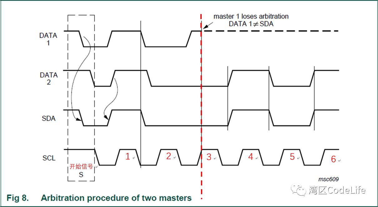
I2C is a true multi-master bus; when two or more masters simultaneously initiate data transmission requests, I2C can control data transmission through conflict detection and arbitration mechanisms. Bus arbitration is determined through a “AND” logic, as shown in the figure below. DATA1 and DATA2 represent the signals from master 1 and master 2. At the same time, both masters initiate data transmission requests. After the START signal, the data that both masters want to transmit matches the data on the SDA data line, so the data from both masters will be transmitted. This continues until the third clock cycle, where master 1 sends a high-level signal while master 2 sends a low-level signal. According to the “AND” logic, after the “AND” operation between master 1 and master 2, the SDA should present a low-level signal, which is opposite to the signal from master 1, causing master 1 to exit the competition, while master 2 gains control of the bus. When the bus is free, master 1 will restart transmission.
– Can Connect Multiple Devices
As mentioned earlier, when the master starts data transmission, it first sends the address of the slave it wishes to communicate with. Since all slave devices connected to I2C have their own addresses, the master can find the desired I2C slave device based on the address information. This shows that the I2C bus can connect multiple devices. The address information is represented by 7 bits, so I2C can connect up to 128 devices.
Conclusion
Thus, the basic definition of the I2C bus has been introduced. Although the I2C bus has advantages such as fewer required lines, easy interference control, and support for multiple masters, it still does not meet the demands of practical use, leading to the development of other bus protocols to replace it. The next article will introduce the equally powerful SPI bus.