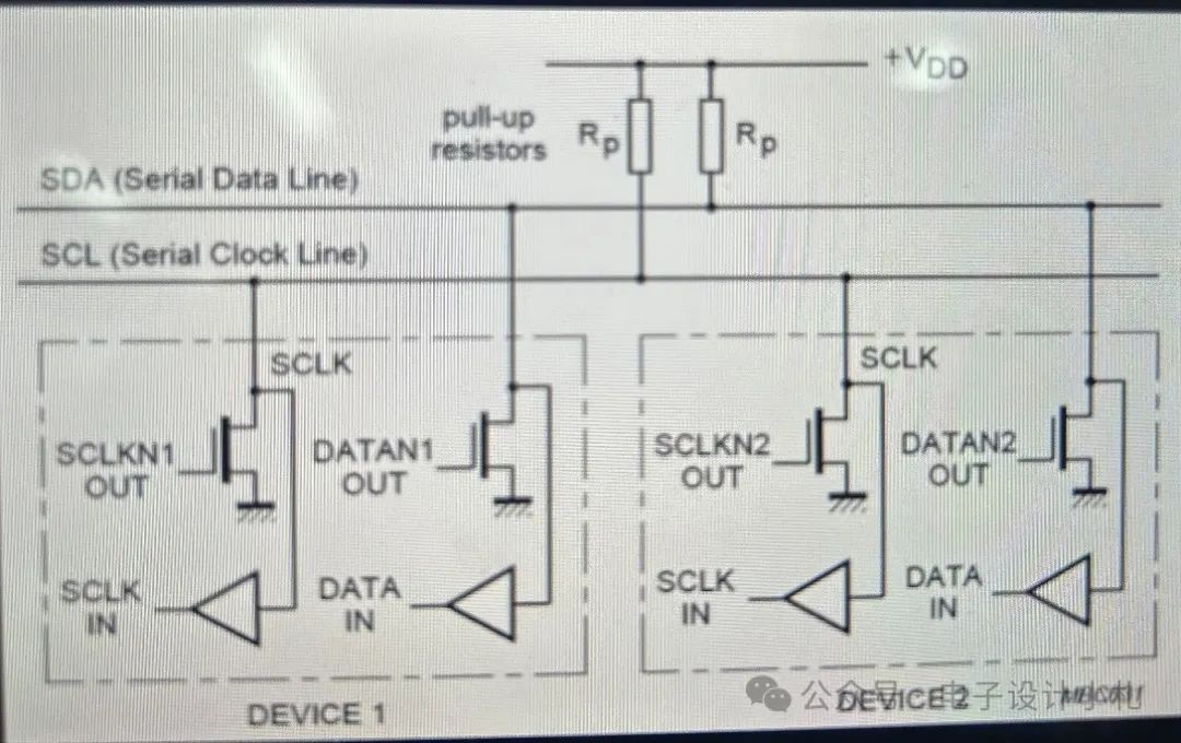
I2C is a common serial communication interface, which is available on most processors. The I2C interface is an open-drain structure, so pull-up resistors are needed in the design to drive the high level. As shown below: Rp is the pull-up resistor, and the dashed box contains the internal I2C controller structure of the chip (for reference). For most chips, the I2C interface can act as either master or slave, so we can see that SCL has both input and output paths in the figure below. When acting as a master, SCL is an output and drives the MOSFET output through the SCLKN1 OUT path; when acting as a slave, it follows the SCLKIN path; similarly, DATA also has two paths..
The above is the internal structure of the I2C interface. So how do we select the pull-up resistor during design? What we commonly see are 10K, 4.7K, 2.2K; in fact, we can determine the value of the pull-up resistor through calculations.
1. Calculation of the Minimum Value of Pull-Up Resistor
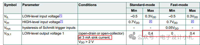
In the manual, we can find the following data: when the sinking current Iol=3mA, VolMAX=0.4V.
We talked about the internal structure of I2C above. When the output is low, it can be simply understood as shown in the figure below: Rds_on is the on-resistance of the MOSFET;
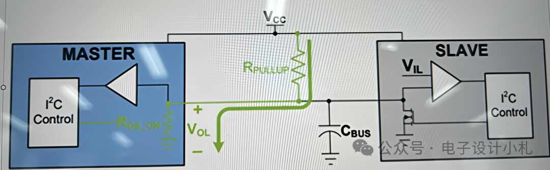
Then the formula for calculating the pull-up resistor is Rp= (VCC-Vol)/Iol;
From the formula, we can see that if Rp is minimized, Vol should take the maximum value;
That is, in the example shown: Iol=3mA, Volmax=0.4V, substituting into the design example allows us to calculate the minimum value.
However, it should be noted that the selected pull-up resistor should not be too small, as a too-small value may lead to an increase in sinking current, which could potentially damage the IO pins over prolonged use and affect the chip’s lifespan.
2. Calculation of the Maximum Value of Pull-Up Resistor
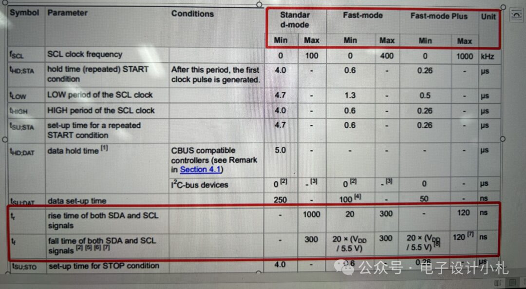
Due to the open-drain structure of I2C, pull-up resistors must be added in the design to drive the high level. Therefore, when the signal changes from low to high, the pull-up power supply VCC will charge the line’s load capacitance through Rp, and the charging time is the rise time. Usually, chips have requirements for the rise time of the I2C bus signal, so this is an important factor to consider when selecting the maximum value of the pull-up resistor. Common I2C interface speeds are 100kbps and 400kbps, corresponding to rise time requirements of 1us and 300ns, which can be found in the I2C protocol, and most chip manuals will specify this.
The total load capacitance on the signal line (to ground) consists of various components, including device pins, PCB trace parasitic capacitance, etc. Typically, the parasitic capacitance values of PCBs have empirical values, and the parasitic capacitance of chip pins will be given in the manual, i.e., Cin; if the RC time constant is too large, the rise time of the signal will be slow, failing to meet data transmission requirements, which may lead to data errors, thus reasonable selection is necessary.
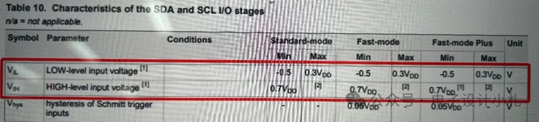
In digital circuits, the IO interface levels are typically defined as:
“Low Level Voltage” VL= 0.3 x Vcc
“High Level Voltage” VH= 0.7 x Vcc
The manual will also specify this; for example, a certain chip manual describes it as follows:
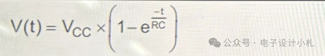
Below is the derivation for calculating Rpmax:
RC circuit step response formula:
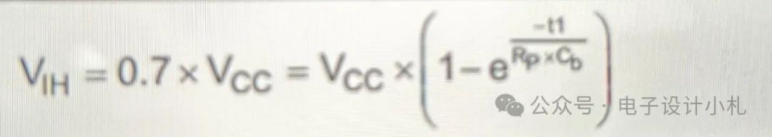
VIH=0.7*VCC
VIL=0.3*VCC
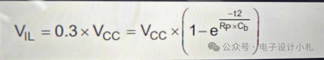
The rise time is the charging time:
Tr = t2-t1
Thus, Rp calculation:
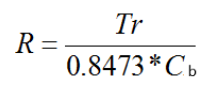 . From this formula, we can see that when Tr takes the maximum value and Cb takes the minimum value, we can calculate the maximum value.
In this formula, tr is the required rise time of the signal, and Cb is the line load capacitance;
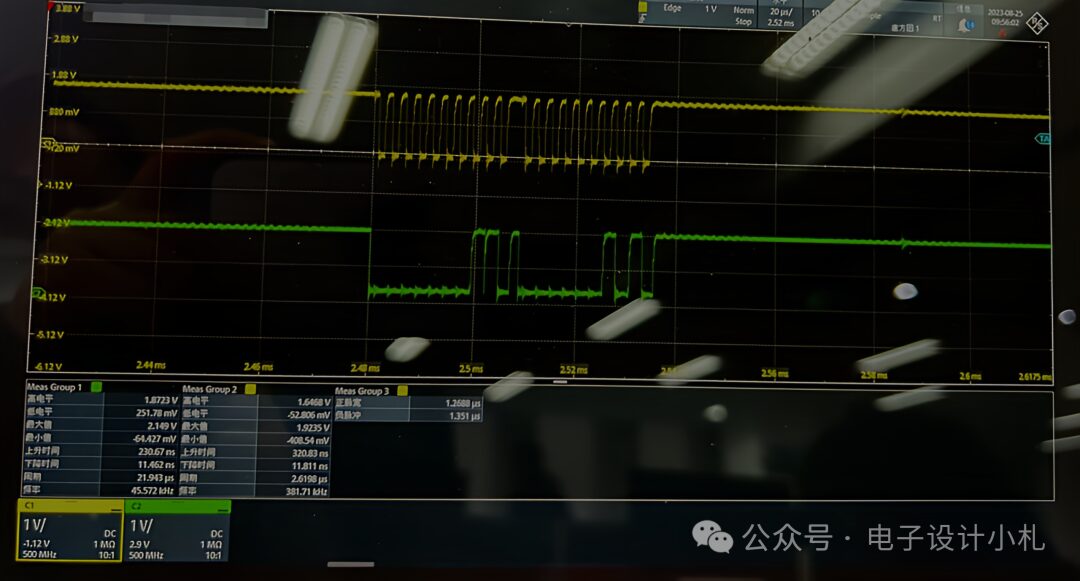
In design, we usually select the pull-up resistor based on empirical values or recommendations from suppliers. However, during a test, it was found that the rise time of the I2C interface SCL exceeded the standard. The selected pull-up resistor was 2.2K, and the rise time reached over 320ns. From the waveform, it can be seen that the rise edge is somewhat slow. After calculation and testing, the pull-up resistor was selected as 1.8K, resulting in a rise time of 265ns, which met the protocol requirements. The following figure shows the waveform exceeding the standard:
We can discuss the I2C protocol further later; let’s have a discussion together~