
Click the Blue Word
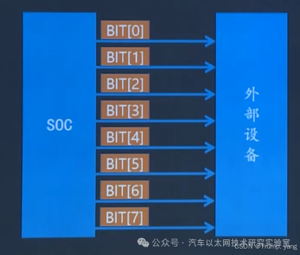
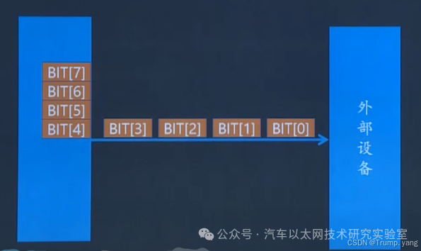
Communication Basics—Parallel and Serial
-
High-Speed Transmission: Because multiple bits can be transmitted simultaneously, parallel communication can theoretically be faster than serial communication. -
Low Latency: Due to the simultaneous transmission of multiple bits, the latency is lower, making it suitable for applications that require quick responses.
-
Signal Interference: When there are many data lines, electromagnetic interference (crosstalk) between the lines can lead to a decrease in signal quality, especially at high frequencies. -
High Cost: Multiple data lines are required, and each line must be precisely matched in length to prevent signal misalignment, making wiring complex and costly. -
Distance Limitations: Because multiple lines must maintain synchronization, signals can easily distort over longer distances, so parallel communication is usually limited to short-distance applications.
-
Simplified Wiring: Only a pair of transmission lines is needed, reducing wiring complexity and lowering design and manufacturing costs. -
Strong Anti-Interference Capability: Because there is only a pair of signal lines, there is little crosstalk between lines, making it suitable for long-distance transmission. Differential signal serial communication (such as RS-485, CAN) has even greater anti-interference capabilities. -
Good Data Synchronization: Serial communication often includes a clock signal (like SPI, I2C) or has its own synchronization mechanism to ensure complete data transmission.
-
Relatively Low Transmission Rate: Since data is transmitted bit by bit, the bit rate is usually lower than that of parallel communication. However, modern high-speed serial communications (like USB 3.0, PCIe, SATA) have improved speed through higher clock frequencies and encoding techniques. -
Higher Latency: Because of bit-by-bit transmission, compared to parallel communication, it may introduce higher latency, especially when handling large data volumes.
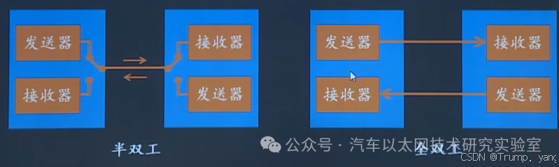
Communication Basics—Simplex and Duplex

Communication Basics—Baud Rate
-
9600
-
19200
-
38400
-
57600
-
115200
-
230400
-
460800
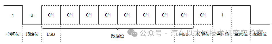
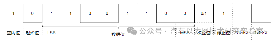
UART Frame Format
-
Start Bit: Sends 1 bit logic 0 (low level) to begin data transmission. -
Data Bits: Can be 5 to 8 bits of data, sending the low bit first and then the high bit, generally, 8 bits (1 byte) is common, with other examples including 7-bit ASCII code. -
Parity Bit: Odd/even parity, with the number of 1s being even (even parity) or odd (odd parity). -
Stop Bit: The stop bit marks the end of data transmission and can be 1/1.5/2 bits of logic 1 (high level). -
Idle Bit: The data line remains high when idle, indicating no data transmission.
Problems with UART
-
RS-232 standard voltage range is typically between -12V and +12V. -
TTL (Transistor-Transistor Logic) UART typically uses 0V (low level) and 3.3V or 5V (high level). -
Some embedded devices may even use 1.8V signal levels.
RS232 Protocol
-
Logic “1” (idle state, usually negative voltage) is between -3V and -15V. -
Logic “0” (active state, usually positive voltage) is between +3V and +15V.
2. Signal Direction and Functions:
-
TXD (Transmit Data): Sending data line. -
RXD (Receive Data): Receiving data line. -
RTS (Request to Send): Request to send. -
CTS (Clear to Send): Clear to send (handshake signal). -
DTR (Data Terminal Ready): Data terminal ready. -
DSR (Data Set Ready): Data set ready. -
GND (Ground): Ground signal.
-
Asynchronous communication: RS-232 uses asynchronous communication, meaning no additional clock signal is needed to synchronize the transmission between the sender and receiver, using start bits, data bits, and stop bits to mark the beginning and end of data frames. -
Baud rate: Defines the number of bits transmitted per second. Common baud rates include 9600, 19200, 38400, 115200 bps, etc.
-
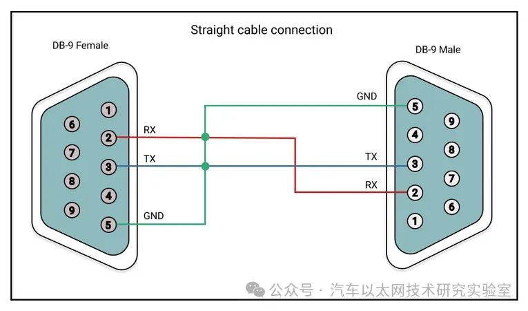
Pin 2: RXD -
Pin 3: TXD -
Pin 5: GND
-
Typically, RS-232 is suitable for short-distance communication (generally less than 15 meters) because the voltage signals decrease as distance increases. -
Transmission rates are generally below 20 kbps.
-
Start Bit: 1 bit, marking the start of the data frame, usually low level (logic 0). -
Data Bits:: 5-9 bits, representing the actual data being transmitted. -
Parity Bit (optional): 1 bit used for error detection. -
Stop Bit: 1-2 bits, marking the end of the data frame, usually high level (logic 1).
-
Computer Serial Port Communication: Early personal computers typically had RS-232 interfaces for connecting modems, mice, printers, and other peripherals. -
Embedded Systems: In some embedded systems and industrial control, RS-232 is used for low-speed, short-distance communication. -
Debugging Interface: As a simple and easy-to-implement communication protocol, RS-232 is commonly used for debugging and firmware updates in embedded systems.
Problems with RS-232
-
RS-232’s transmission distance is typically no more than 15 meters. As distance increases, the voltage signals gradually attenuate, leading to unstable or lost data transmissions. -
In long-distance transmissions, signals may be interfered with or generate errors, making it unsuitable for remote communication scenarios.
-
RS-232 has a low transmission rate, typically below 20 kbps, with a maximum support of 115.2 kbps. Compared to modern interfaces like USB and Ethernet, RS-232 cannot meet high-bandwidth application needs. -
For applications requiring high-speed data transmission (such as video and audio data), RS-232’s bandwidth limitations are particularly evident.
-
RS-232 uses single-ended signal transmission, with signals transmitted over one line and the other serving as a ground reference. This method is easily affected by noise and electromagnetic interference, especially in industrial environments or long-distance transmissions. -
In contrast, protocols like RS-485 use differential signal transmission, which has stronger anti-interference capabilities and is suitable for long-distance communication.
-
RS-232 has multiple connector standards, such as DB9 and DB25, and the pin definitions may differ between devices. Therefore, special adapters or cables may be needed, increasing connection complexity. -
Furthermore, due to the lack of a unified electrical interface standard, different devices may have inconsistent voltage levels (-12V to +12V), which can lead to communication failures or even damage when directly connected.
-
RS-232 only supports point-to-point communication, meaning it can only connect two devices. This limitation makes it difficult to expand in multi-device communication scenarios. -
Modern communication demands often involve network communication among multiple devices, while protocols like RS-485 can support multipoint communication.
RS-485 Protocol
-
RS-485 uses differential signal transmission, meaning data is transmitted through two signal lines (marked A and B), with the signal being the voltage difference between the two lines. -
When the voltage on line A is higher than that on line B, it represents logic