Bus
Buses are everywhere. Signals in this world are the same, but there are thousands of buses, which can be quite confusing.
In general, there are three types of buses: internal buses, system buses, and external buses. Internal buses connect various peripheral chips with the processor within a microcomputer; system buses connect plug-in boards with the system board; and external buses connect the microcomputer with external devices, allowing for information and data exchange between the microcomputer and other devices.
In addition to buses, there are some interfaces that are a collection of multiple buses, or simply put, they accept any incoming signals.
SPI
SPI (Serial Peripheral Interface): A synchronous serial bus method proposed by MOTOROLA. It is a high-speed synchronous serial port. It uses a 3 to 4 wire interface, allowing independent and synchronous transmission and reception.
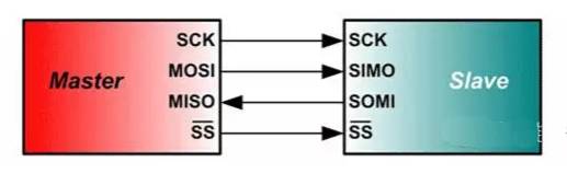
Due to its powerful hardware capabilities, SPI is widely used in smart instruments and measurement control systems composed of microcontrollers. If speed is not a critical requirement, using SPI bus mode is a good choice. It saves I/O ports, increases the number of peripherals, and improves system performance. The standard SPI bus consists of four lines: Serial Clock Line (SCK), Master Input/Slave Output Line (MISO), Master Output/Slave Input Line (MOSI), and Chip Select Signal (CS). Some SPI interface chips come with an interrupt signal line or may not have MOSI.
The SPI bus consists of three signal lines: Serial Clock (SCLK), Serial Data Output (SDO), and Serial Data Input (SDI). The SPI bus can connect multiple SPI devices. The device providing the SPI serial clock is the SPI master, while the other devices are SPI slaves. Full-duplex communication can be achieved between master and slave devices, and if there are multiple slave devices, an additional slave select line can be added. If simulating the SPI bus with general I/O ports, at least one output port (SDO), one input port (SDI), and another port depending on the type of device being implemented are required. If implementing master-slave devices, both input and output ports are needed; if only a master device is implemented, only an output port is needed; and if only a slave device is implemented, only an input port is needed.
I2C
I2C (Inter-Integrated Circuit): A two-wire serial bus developed by PHILIPS for connecting microcontrollers and their peripheral devices.
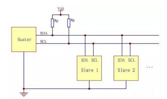
The I2C bus uses two lines (SDA and SCL) to transmit information between the bus and devices, enabling serial communication between microcontrollers and external devices or bidirectional data transfer between master and slave devices. I2C is an open-drain output, and most I2C devices are two-wire (clock and data), generally used for transmitting control signals.
I2C is a multi-master bus, so any device can act as a master and control the bus. Each device on the bus has a unique address, allowing it to operate as either a transmitter or receiver based on its capabilities. Multiple microcontrollers can coexist on the same I2C bus.
UART
UART: Universal Asynchronous Receiver-Transmitter, completing bidirectional communication at standard baud rates, but slower.
The UART bus is an asynchronous serial port, thus generally more complex than the previous two synchronous ports, typically consisting of a baud rate generator (which generates a baud rate equal to 16 times the transmission baud rate), a UART receiver, and a UART transmitter. The hardware consists of two wires, one for sending and one for receiving.
UART is used for controlling communication between computers and serial devices. It is important to note that it provides an RS-232C data terminal device interface, allowing the computer to communicate with modems or other serial devices that use the RS-232C interface. As part of the interface, UART also offers the following functions:
Converting parallel data sent from the computer into an output serial data stream. Converting serial data received from external sources into bytes for internal parallel data use. Adding parity bits to the output serial data stream and performing parity checks on the incoming data stream. Adding start and stop markers to the output data stream and removing them from the received data stream. Handling interrupt signals from keyboards or mice (both of which are serial devices). Managing synchronization issues between the computer and external serial devices. Some advanced UARTs also provide input/output data buffers; the newest UARTs, such as the 16550, can store 16 bytes of data in their buffer before the computer processes it, while the typical UART is 8250. Nowadays, if you purchase a built-in modem, it typically contains a 16550 UART.
Comparing SPI, I2C, and UART
Both SPI and I2C are communication methods for short distances, typically between chips or other components like sensors and chips. SPI and I2C are used for on-board communication, with I2C sometimes used for inter-board communication, but the distance is very short. For example, some touch screens and mobile LCD screens often use I2C. I2C can replace standard parallel buses and can connect various integrated circuits and functional modules. I2C is a multi-master bus, allowing any device to act as a master and control the bus. Each device on the bus has a unique address and can operate as either a transmitter or receiver based on its capabilities. Multiple microcontrollers can coexist on the same I2C bus, and both lines are low-speed transmission.
UART, on the other hand, is used for communication between two devices, such as a microcontroller-based device and a computer. This type of communication can be long-distance. UART is faster than the previous two, with speeds reaching up to about 100K, used for communication between computers and devices or between computers. However, its effective range is not very long, approximately 10 meters. The advantages of UART include wide support and simple program design structure. With the development of USB, UART is gradually declining.
I2S
I2S (Inter-IC Sound Bus) is a bus standard developed by Philips for audio data transmission between digital audio devices.
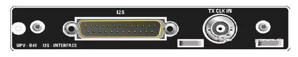
I2S typically uses three lines (in addition to clock and data, there is also a signal for selecting left or right channel), primarily used for transmitting audio signals, such as in STB, DVD, MP3, etc.
The I2S standard specifies both hardware interface specifications and the format of digital audio data. I2S has three main signals: 1) Serial Clock SCLK, also called Bit Clock (BCLK), corresponding to each bit of digital audio data, with one pulse for each. The frequency of SCLK = 2 × sampling frequency × number of sampling bits. 2) Frame Clock LRCK (also called WS), used to switch data between left and right channels. LRCK = “1” indicates that left channel data is being transmitted, whereas “0” indicates that right channel data is being transmitted. The frequency of LRCK equals the sampling frequency. 3) Serial Data SDATA, which represents audio data in binary two’s complement format.
Sometimes, to achieve better synchronization between systems, an additional signal MCLK, known as the Master Clock or System Clock (Sys Clock), is transmitted, which is 256 or 384 times the sampling frequency.
GPIO
GPIO (General Purpose Input Output) or bus expander simplifies the expansion of I/O ports using industrial standard I2C, SMBus, or SPI interfaces.
When a microcontroller or chipset does not have enough I/O ports, or when the system requires remote serial communication or control, GPIO products can provide additional control and monitoring capabilities. Each GPIO port can be configured as input or output via software. Maxim’s GPIO product line includes GPIOs with 8 to 28 ports, offering push-pull output or open-drain output. They come in a compact 3mm x 3mm QFN package.
Advantages of GPIO (Port Expander):
Low power: GPIO has lower power consumption (about 1μA, while the μC operates at 100μA).
Integrated IIC Slave Interface: GPIO includes an IIC slave interface that can operate at full speed even in standby mode.
Small package: GPIO devices provide the smallest package size — 3mm x 3mm QFN!
Low cost: You don’t pay for unused features!
Quick time to market: No need to write additional code or documentation, and no maintenance work required!
Flexible light control: Built-in multiple high-resolution PWM outputs.
Pre-determined response time: Shortens or determines the response time between external events and interrupts.
Better lighting effects: Matched current output ensures uniform display brightness.
Simple wiring: Only 2 IIC lines or 3 SPI lines are needed.
SDIO
SDIO is an extension interface of the SD type, which can connect not only SD cards but also devices supporting the SDIO interface; the socket’s purpose is not limited to inserting storage cards. Devices supporting the SDIO interface, such as PDAs, laptops, etc., can connect to GPS receivers, Wi-Fi or Bluetooth adapters, modems, LAN adapters, barcode scanners, FM radios, TV receivers, RFID readers, or digital cameras, among other devices using the SD standard interface.
The SDIO protocol evolved and upgraded from the SD card protocol, retaining many aspects of the SD card’s read/write protocol, while also adding CMD52 and CMD53 commands on top of it. An important distinction between the SDIO and SD card specifications is the addition of a low-speed standard, aimed at supporting low-speed I/O capabilities with minimal hardware. Low-speed cards support applications like modems, barcode scanners, and GPS receivers, while high-speed cards support network cards, TV cards, and “combo” cards, which refer to memory + SDIO.
Another important difference between the SDIO and SD card specifications is the addition of a low-speed standard. SDIO cards only require SPI and 1-bit SD transmission mode. The goal of low-speed cards is to support low-speed I/O capabilities with minimal hardware costs, while low-speed cards support applications like MODEM, barcode scanners, and GPS receivers. For combo cards, full-speed and 4BIT operations are mandatory for both the card’s memory and the SDIO portion.
In non-combo SDIO devices, the maximum speed is limited to 25M, while combo cards can achieve speeds exceeding 25M, similar to the maximum speed of SD cards.
CAN
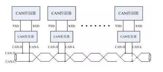
CAN, short for “Controller Area Network,” is one of the most widely used field buses internationally. Initially, CAN was designed for microcontroller communication in automotive environments, exchanging information between various electronic control units (ECUs) in vehicles, forming an automotive electronic control network. For example, engine management systems, transmission controllers, instrument equipment, and electronic backbone systems all embed CAN control devices.
In a single network constructed with CAN bus, theoretically, countless nodes can be connected. In actual applications, the number of nodes is limited by the electrical characteristics of the network hardware. For instance, when using the Philips P82C250 as a CAN transceiver, up to 110 nodes are allowed on the same network. CAN can provide data transmission rates of up to 1Mbit/s, making real-time control very easy. Additionally, the hardware’s error detection capabilities enhance CAN’s resistance to electromagnetic interference.
Characteristics of CAN Bus:
1) It can operate in a multi-master mode, allowing any node on the network to actively send information to other nodes at any time, regardless of master or slave, providing flexible communication.
2) Nodes on the network can be assigned different priorities to meet various real-time requirements.
3) It employs a non-destructive bit arbitration bus structure mechanism, where if two nodes transmit information simultaneously, the node with the lower priority will actively stop sending data while the higher priority node continues unaffected.
4) It supports point-to-point, one-to-many, and global broadcast data transmission methods.
5) The maximum direct communication distance can reach up to 10km (at speeds below 4Kbps).
6) The maximum communication rate can reach 1MB/s (at which point the maximum distance is 40m).
Focus | Open | Share
This is a community of professional antenna and RF circuit engineers and seasoned hardware engineers.
We love design, testing, and this wonderful microwave world.
We have the best people, the best atmosphere, and the most insightful perspectives.
We deeply believe that RF professionals take pride in teaching, imparting knowledge, and solving problems!
Join the “RFsister RF Clinic”
Step 1: Follow @RFsister on WeChat public account.

Step 2: Add WeChat “rfsister01” as a friend,
Note “RF Clinic” to join the group.

Source: 21IC; RFsister Edited and Compiled
Reprint Statement: This article aims to provide industry news reading for the RF technology community. If there are any inaccuracies or infringement issues, please contact us immediately for resolution! Respect knowledge, respect originality!
Submission Email: [email protected]