In digital signal processing and FPGA development, fixed-point design is a crucial step from algorithm to hardware implementation. Algorithms in MATLAB are typically modeled and verified using floating-point numbers, but FPGA hardware often only supports fixed-point operations. There are significant differences in data precision, rounding methods, and overflow handling between the two, leading to discrepancies between simulation results and actual hardware performance.
MATLAB provides the Fixed-Point Converter, which helps engineers simulate the fixed-point behavior of FPGA during the algorithm design phase, allowing timely adjustments to data word length through precision error analysis. This article will provide a step-by-step example of how to use the MATLAB Fixed-Point Toolbox to set up a fixed-point simulation process, accurately replicating the FPGA computation process and laying a solid foundation for subsequent hardware deployment.
Step 1: Preparation
First, you need to write the floating-point algorithm function in MATLAB and prepare the corresponding test data. The test data is an essential part of the subsequent fixed-point conversion and simulation, and it can also be used for error analysis. For example, prepare the following function and test data for a/b, where the test data is generated using the randn function, as shown in the commented code.
function y = fx_divide(a,b)
    y = a./b;
end
% a=randn(1,10);
% b=randn(1,10);
a=[0.4885   -0.5309   -0.4739    0.4533   -0.4348   -1.5504   -1.6039   -0.7868    1.8679    2.2972];
b=[-0.0669   -1.5552    0.0050    0.6900    2.5733    1.7257   -0.4008   -1.1979   -0.4931   -1.1326];
y = fx_divide(a,b);
Step 2: Import Functions and Test Data
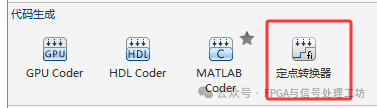
Open the app shown in the figure below in MATLAB.
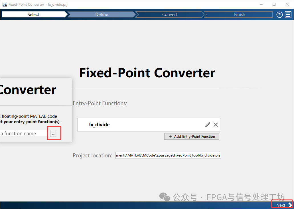
Click the three dots in the red box to import the function, then click the next button at the bottom right.
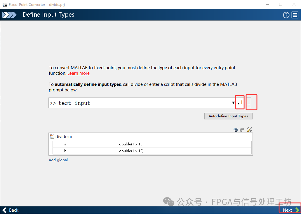
Similarly, click the three dots to import the test data, then press the enter key. When the types of input variables a and b appear, click next.
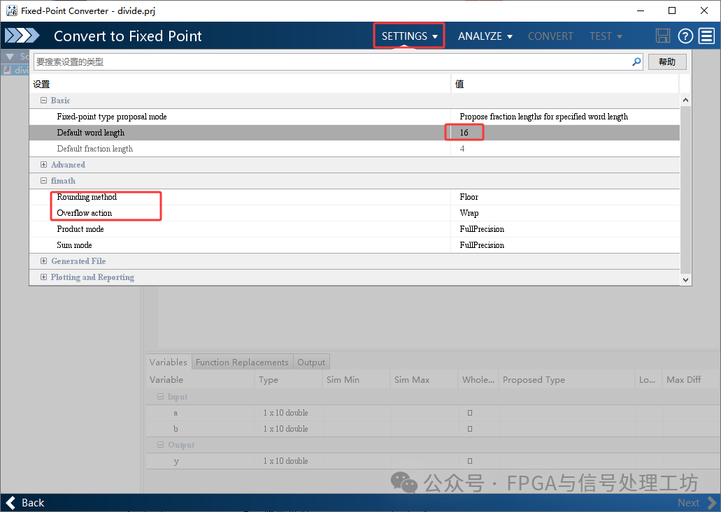
Click SETTINGS to set the word length, rounding mode, overflow mode, etc. You can modify these settings as needed; the example keeps the defaults.
Step 3: Analyze and Convert
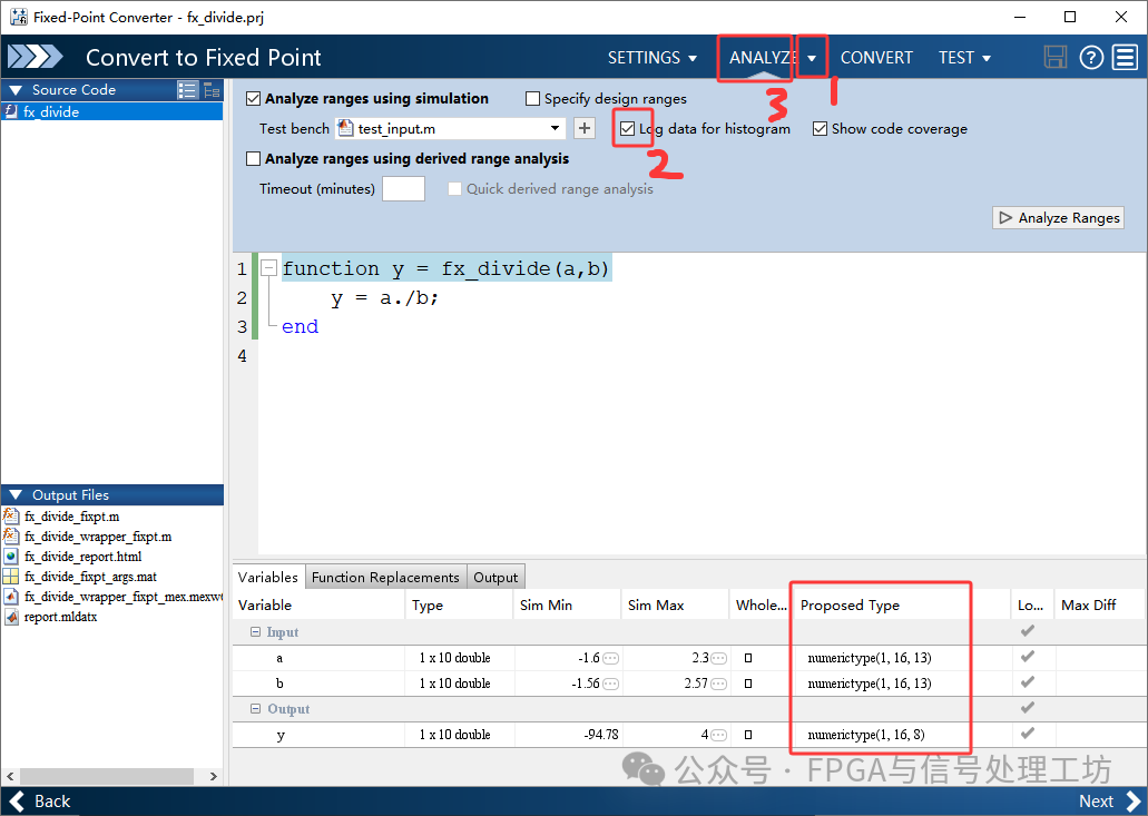
Follow the sequence shown in the figure below to perform the analysis. After the analysis, a recommended fixed-point format will be provided.
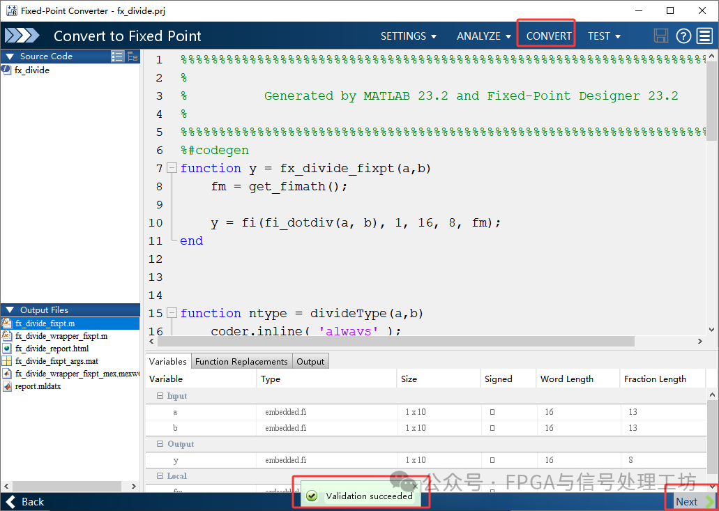
Then click CONVERT, and upon success, click NEXT.
Step 4: Testing
Follow the steps below to test, which will display the outputs of the floating-point model and the fixed-point model, as well as the error curves between the two.
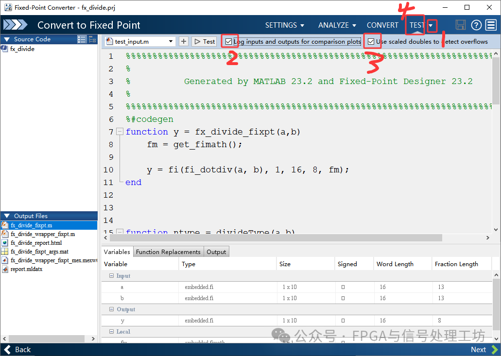
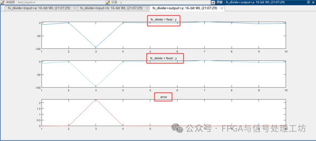
Finally, click NEXT to complete the conversion.
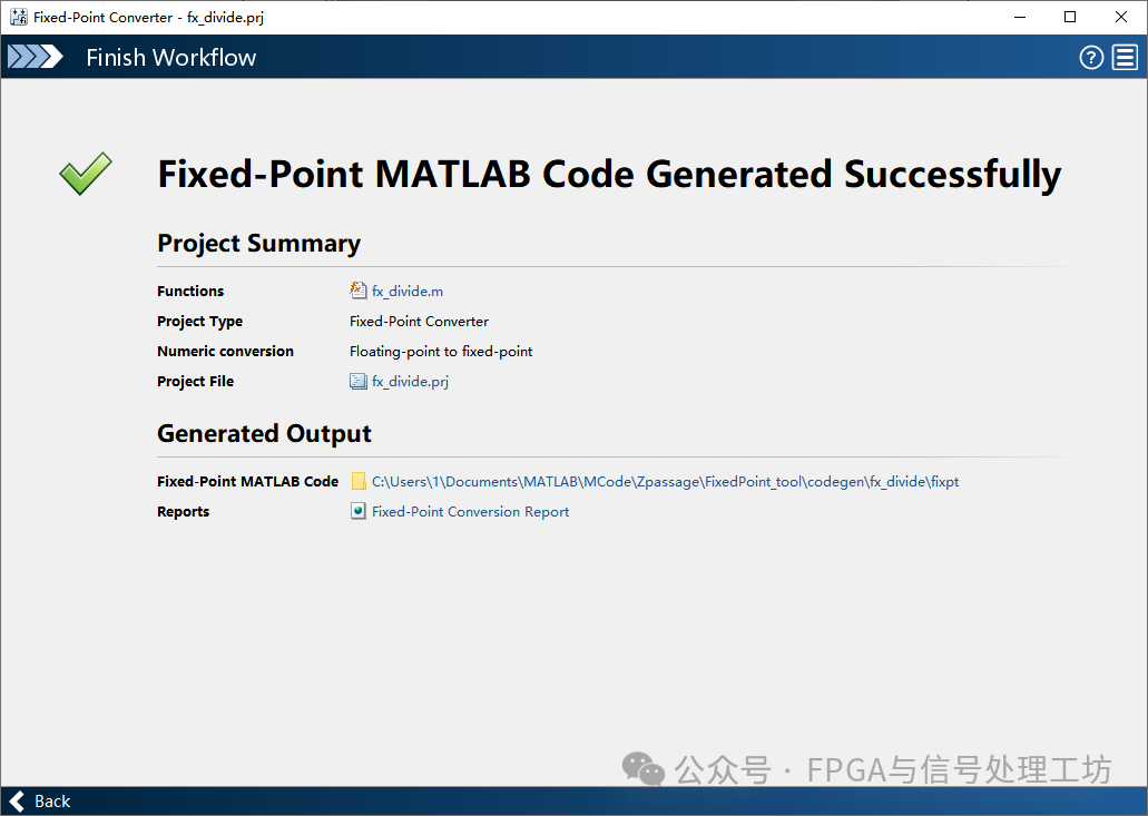
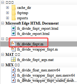
The converted floating-point model will be the function with the suffix fixpt under the conversion project.
Conclusion
The MATLAB Fixed-Point Converter tool can efficiently automate the conversion from floating-point models to fixed-point models and provides error analysis functionality for both floating-point and fixed-point results. By comparing the output differences between the two, users can intuitively assess the precision loss caused by fixed-point representation and flexibly adjust data word length and quantization schemes to achieve the best balance between hardware resources and computational precision.
-END-
If this article has been helpful to you, please remember tofollow our public account, which will continue to update knowledge related to FPGA and signal processing. Thank you!
If this has been helpful to you, please light up the heart at the bottom of the article♡, thank you!