▲ For more exciting content, please click on the blue text above to follow us!
Communication Methods Between Devices
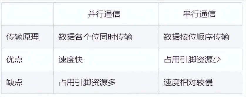
Generally, communication methods between devices can be divided into parallel communication and serial communication. The differences between parallel and serial communication are shown in the table below.
Classification of Serial Communication
1. According to the direction of data transmission, it can be divided into:
-
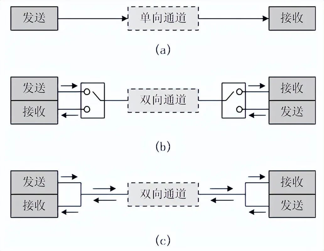
Simplex: Data transmission supports only one direction;
-
Half-duplex: Allows data to be transmitted in both directions. However, at any given moment, data can only be transmitted in one direction; it is essentially a switched-direction simplex communication; it does not require independent receiving and transmitting ends, and both can use one port together.
-
Full-duplex: Allows data to be transmitted simultaneously in both directions. Therefore, full-duplex communication is a combination of two simplex communication methods and requires independent receiving and transmitting ends.
2. According to the communication method, it can be divided into:
-
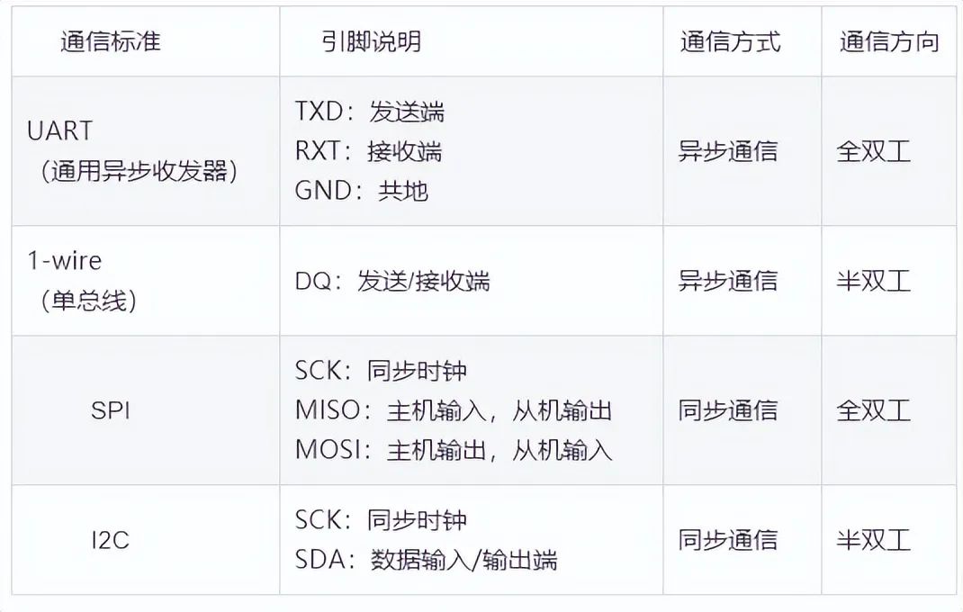
Synchronous communication: Transmission with clock synchronization signal. For example: SPI, IIC communication interfaces.
-
Asynchronous communication: Without clock synchronization signal. For example: UART (Universal Asynchronous Receiver-Transmitter), single bus.
In synchronous communication, a signal line is used to transmit signals above the transmitting and receiving devices, and both parties coordinate and synchronize data under the drive of the clock signal. For example, in communication, both parties usually agree to sample the data line at the rising or falling edge of the clock signal.
In asynchronous communication, no clock signal is used for data synchronization; they directly intersperse some signal bits for synchronization into the data signal or package the subject data to transmit data in the format of data frames. The transmission rate (also known as baud rate) must also be agreed upon between both parties to ensure better synchronization. Common baud rates include 4800bps, 9600bps, 115200bps, etc.
In synchronous communication, the content transmitted by the data signal is mostly valid data, while asynchronous communication will include various identifiers of the data frame, thus synchronous communication is more efficient. However, the clock of both parties in synchronous communication allows for small errors, and a slight clock error may lead to data confusion, while asynchronous communication allows for larger clock errors.
Common Serial Communication Interfaces
Basic STM32 Serial Communication
The STM32 serial communication interface has two types: UART (Universal Asynchronous Receiver-Transmitter) and USART (Universal Synchronous/Asynchronous Receiver-Transmitter). For the large-capacity STM32F10x series chips, there are 3 USARTs and 2 UARTs.
UART Pin Connection Method
-
RXD: Data input pin, data reception;
-
TXD: Data output pin, data transmission.
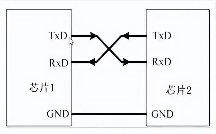
For the connection between two chips, the two chips share a common ground, and TXD and RXD are cross-connected. Here, the cross-connection means that the RXD of chip 1 connects to the TXD of chip 2, and the RXD of chip 2 connects to the TXD of chip 1. In this way, TTL level communication can be established between the two chips. For examples of STM32 serial communication with the 51 microcontroller, please refer to: STM32 and 51 Microcontroller Serial Communication Examples.
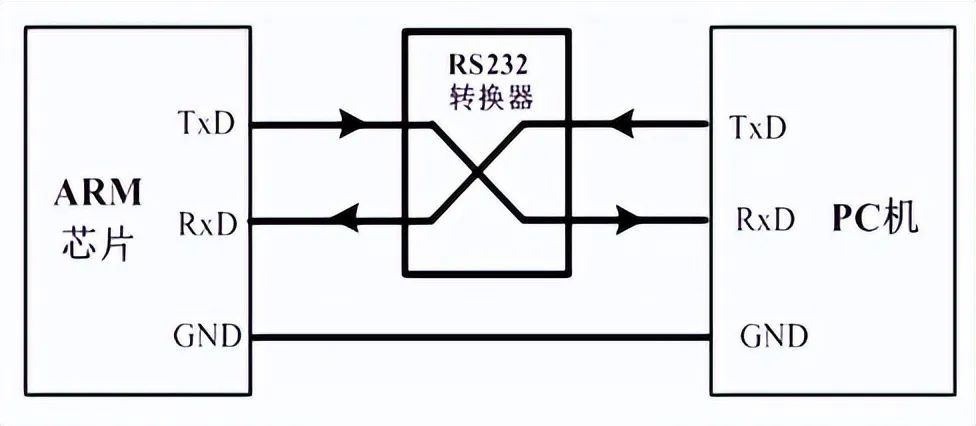
If the chip is connected to a PC (or host), in addition to sharing a common ground, it cannot be directly cross-connected. Although both the PC and the chip have TXD and RXD pins, the PC (or host) typically uses an RS232 interface (usually DB9 packaging), so direct cross-connection is not possible. The RS232 interface has 9 pins (or pins), and usually, TxD and RxD are obtained through level conversion. Therefore, to enable direct communication between the chip and the RS232 interface of the PC, the input and output ports of the chip must also be level-converted to RS232 type before cross-connection.
After level conversion, the voltage standards of the chip’s serial port and RS232 are different:
-
The microcontroller’s voltage standard (TTL level): +5V represents 1, 0V represents 0;
-
RS232 voltage standard: +15/+13 V represents 0, -15/-13 represents 1.
The communication structure diagram of devices using the RS-232 communication protocol standard serial port is as follows:
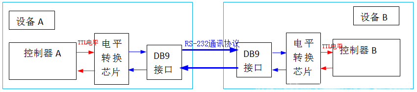
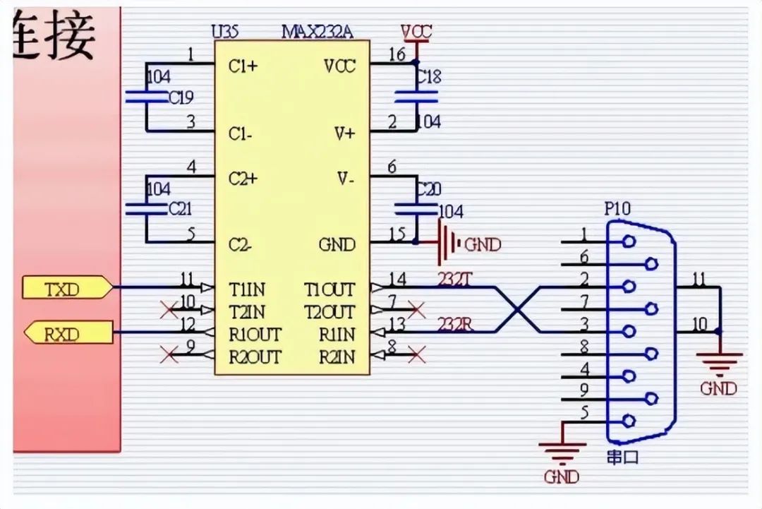
Therefore, communication between the microcontroller serial port and the PC serial port should follow the connection method below: Between the microcontroller serial port and the RS232 port provided by the host, a level conversion circuit (such as the Max232 chip in the diagram below) should be used to realize the conversion between TTL level and RS232 level. For examples of communication between STM32 and PC, please refer to: STM32 Example – Using a Button to Control Serial Data Transmission, with code attached at the end.
Introduction to RS232 Serial Port
The 9-pin interface at the back of a desktop computer is the COM port (serial port), widely used in industrial control and data acquisition. In the above image, the rightmost is the serial port interface collectively referred to as RS232 interface, which is a common DB9 packaging.
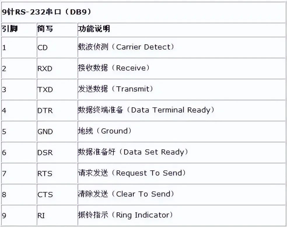
Only two pins are involved in the communication process.
-
Pin 2: Computer input RXD
-
Pin 3: Computer output TXD. Through pins 2 and 3, full-duplex (simultaneous send and receive) asynchronous serial communication can be achieved.
-
Pin 5: Ground.
The P3 port of the microcontroller has two multiplexed interfaces RXD and TXD. This is the transceiver port for the microcontroller to perform serial communication, and the connection should correspondingly connect to the computer’s TDX and RDX. Note: The voltage standards of the microcontroller and RS232 are different.
The voltage standard of the microcontroller is TTL level: +5V represents 1, 0V represents 0.
The voltage standard of RS232 is +15/+13 V represents 1, -15/-13 represents 0.
Therefore, communication between the microcontroller and the computer serial port should follow the connection method below:
Between the microcontroller and the RS232 port provided by the host, a level conversion circuit (the Max232 chip in the diagram above) should be used to achieve conversion between TTL level and RS232 level. The connection method diagram between the PC serial port and the microcontroller serial port is as follows:

Note that these two DB9: DB91 is on the computer and DB92 is soldered on the microcontroller experimental board.
The cross-connection here means that RXD of DB91 connects to TXD of DB92.
RXD of DB92 connects to TXD of DB91, thus cross-connected. If the computer does not have an RS232 port and only has a USB port, a serial port adapter can be used to convert to a serial port, as shown in the diagram below.
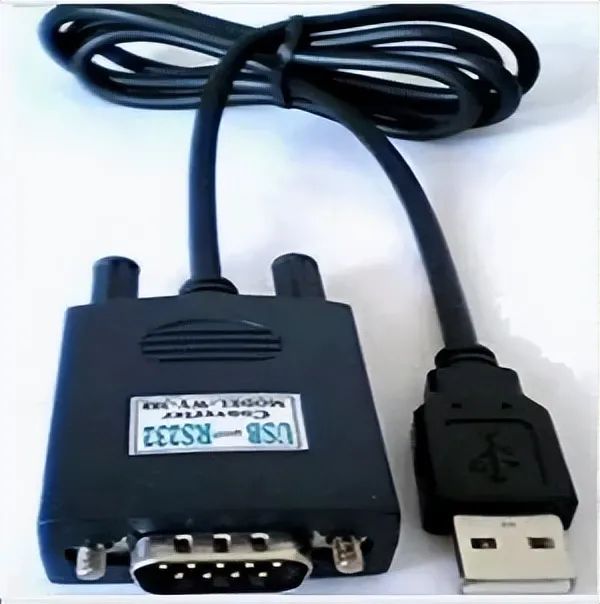
At this time, it is necessary to install the serial port driver program on the computer host.
Note that this driver program drives the PL2303 chip (inside the big head in the above image) to convert RS232 information into USB information.
The following image shows the internal structure of the above image:
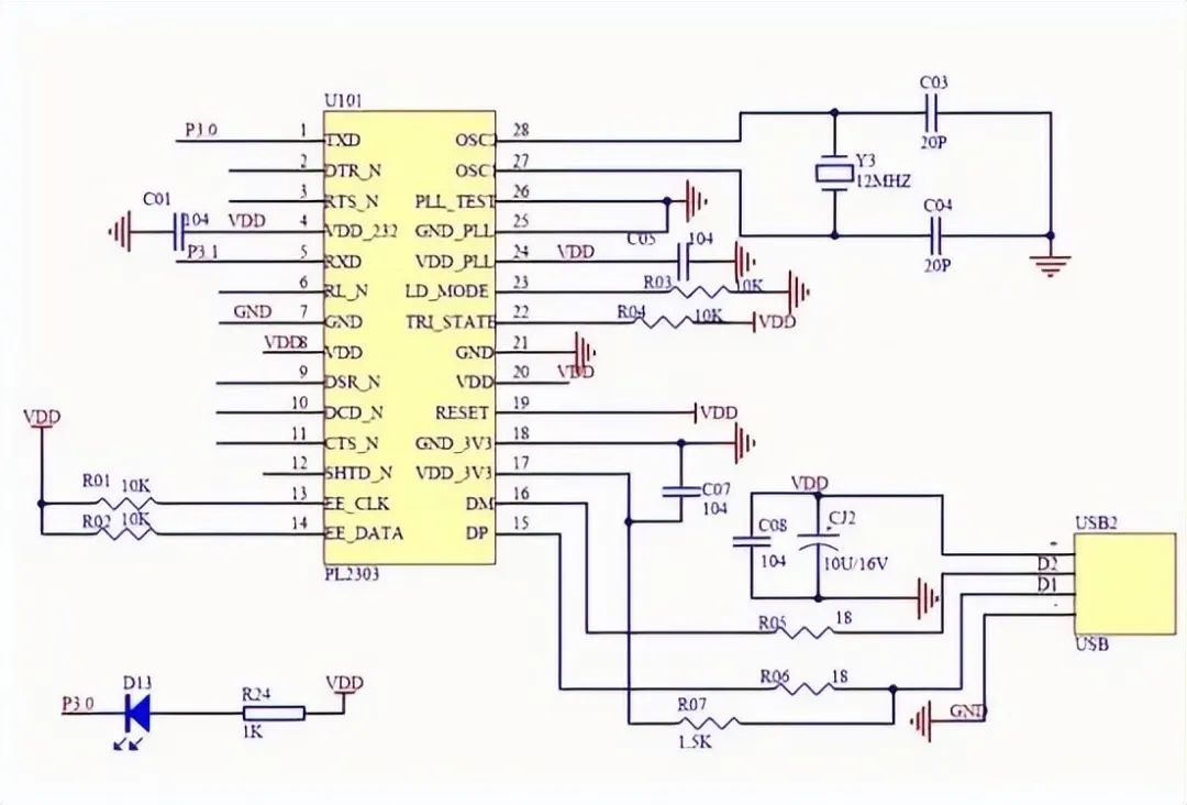
Using serial communication is simpler than USB because serial communication has no protocol and is easy to use.
Features of STM32’s UART
-
Full-duplex asynchronous communication;
-
Fractional baud rate generator system provides precise baud rates. Shared programmable baud rate for sending and receiving, up to 4.5Mbits/s;
-
Programmable data word length (8 bits or 9 bits);
-
Configurable stop bits (supports 1 or 2 stop bits);
-
Configurable DMA multi-buffer communication;
-
Separate transmitter and receiver enable bits;
-
Detection flags:
-
① Receiver buffer
-
② Transmitter buffer empty
-
③ Transmission end flag;
-
Multiple interrupt sources with flags to trigger interrupts;
-
Others: Parity control, four error detection flags.
Serial Communication Process
UART Parameters in STM32
The data packet for serial communication is transmitted from the sending device through its TXD interface to the RXD interface of the receiving device. The packet format of both parties must be consistent to successfully send and receive data.
Parameters that need to be defined for asynchronous communication in STM32 include: start bit, data bits (8 bits or 9 bits), parity bit (9th bit), stop bits (1, 1.5, or 2 bits), baud rate settings.
The data packet for UART serial communication is framed, with a common frame structure of: 1 start bit + 8 data bits + 1 parity bit (optional) + 1 stop bit. As shown in the diagram below:
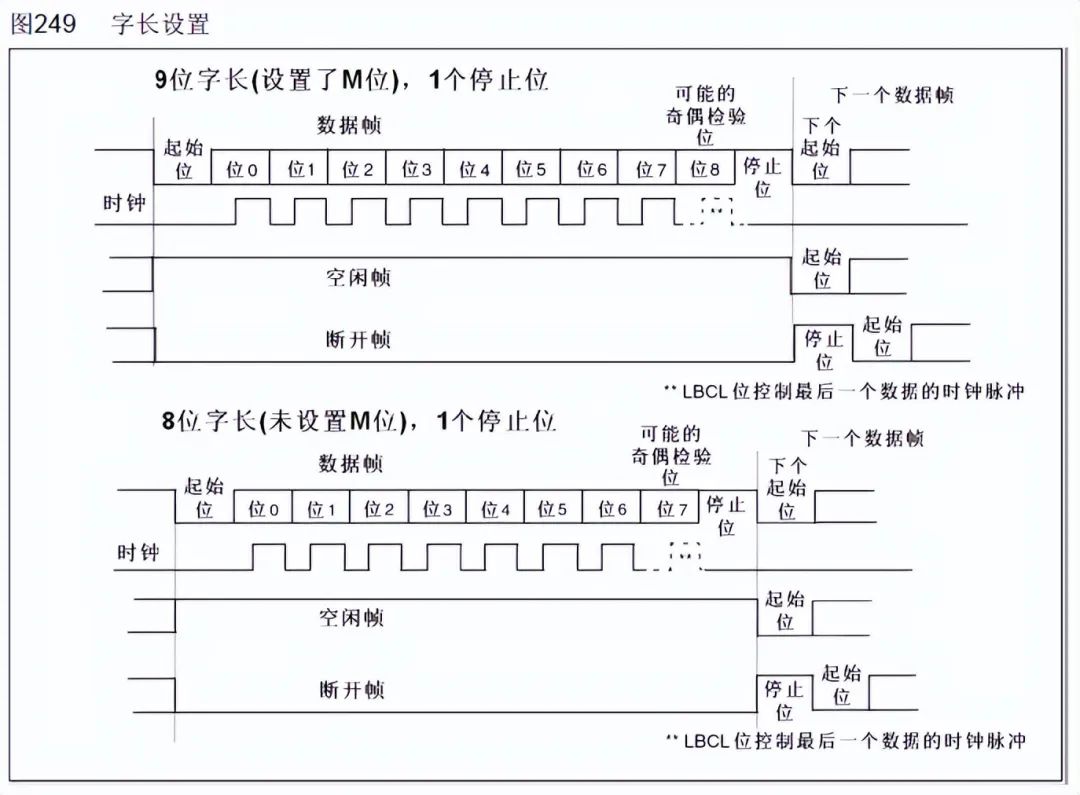
The parity bit can be either odd or even, which is a simple method for error checking. Odd parity means that the total number of 1s in the entire 9 bits (including data bits and parity bit) must be odd; even parity means that the total number of 1s in the entire 9 bits must be even.
In addition to odd (odd) and even (even) parity, there are also: 0 parity (space), 1 parity (mark), and no parity (noparity). 0/1 parity means that regardless of the content of the valid data, the parity bit is always 0 or 1.
UART (USART) Block Diagram
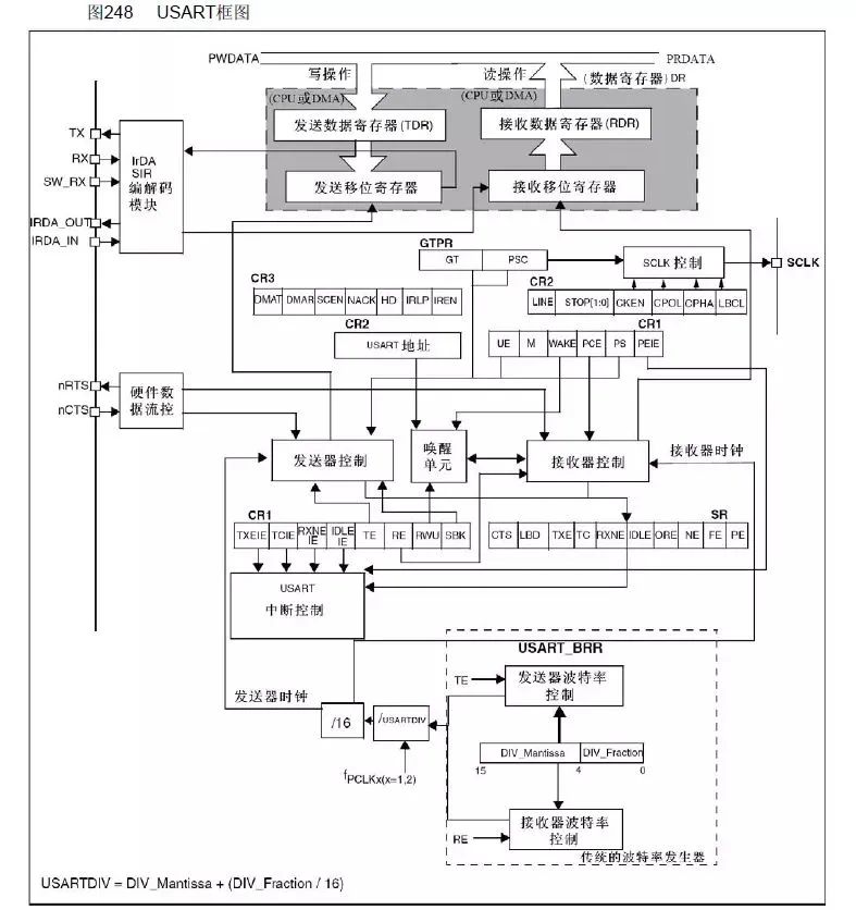
This block diagram is divided into upper, middle, and lower parts. This article briefly discusses the content of each part; for specifics, please refer to the description in the “STM32 Chinese Reference Manual”.
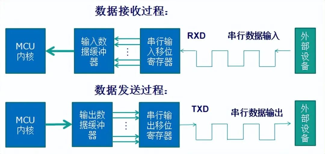
The upper part of the block diagram shows that data enters the receive shift register from RX, then enters the receive data register, and is ultimately read by the CPU or DMA; data from the CPU or DMA is sent to the send data register, then enters the send shift register, and is finally sent out through TX.
However, both sending and receiving in UART require baud rate control. How is the baud rate controlled?
This brings us to the lower part of the block diagram, where there is an incoming arrow for both the receive shift register and the send shift register, connecting to the receiver control and sender control, respectively. This means that although asynchronous communication does not have a clock synchronization signal, a clock signal is provided internally in the serial port for control. The receiver clock and sender clock are controlled by the same control unit, meaning they share a common baud rate generator. It can also be seen how the receiver clock (generator clock) and USRRTDIV are calculated.


This article is a network reprint, and the copyright belongs to the original author. If there are copyright issues with any videos, images, or text used in this article, please leave a message at the end of the article, and we will handle it as soon as possible! The content of this article represents the original author’s views and does not represent the views of this public account or its authenticity.


Recommended Reading
In-Depth | PCB Layout and Design of Buck ConvertersIn-Depth | How to Choose the Right Power Chip, Have You Learned It?In-Depth | Why Decoupling Capacitors Usually Choose 100nF Instead of Other Capacitor Values?In-Depth | Understanding the Continuous Collector Current IC of IGBT
Add WeChat and reply “Join Group“
To add you to the technical exchange group!
Domestic Chips | Automotive Electronics | IoT | New Energy | Power Supply | Industry | Embedded…..
Reply any content you want to search in the public account, such as keywords, technical terms, bug codes, etc., and you can easily get professional technical content feedback related to it. Try it out!
If you want to see our articles regularly, you can go toour homepage, click the three small dots in the upper right corner, and click “Set as Star”.
Welcome to scan and follow