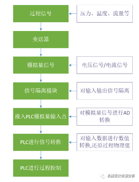
Analog signals are the most basic process signals in automation process control systems, such as pressure, temperature, flow, etc. These signals are input forms that are transmitted through transmitters, converting the detected signals into standardized voltage and current signals, and sending these signals in real-time to the controller (PLC).
PLCs convert these analog signals into internal numerical values through calculations, thus enabling system monitoring and control. The process from physical signals on-site to numerical signals processed internally by the PLC involves several steps:
From the above PLC analog signal input process, it can be seen that the input of analog signals in automation process control systems is very complex. However, in current industrial sites, the processing of analog signals is mostly done using current signal transmission methods. Compared to voltage signal methods, current signals have stronger anti-interference capabilities, longer transmission distances, and more stable signals.
Here, we will provide a simple breakdown of the conversion process of analog signals by PLCs.
PLC converts analog signals
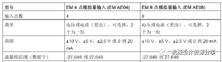
▲ Siemens S7-200SMART PLC analog module for analog signal conversion range
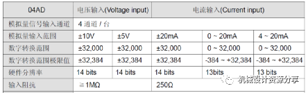
▲ Delta DVP series analog module for analog signal conversion range
From the above, we can see:
1. After the analog signal is connected to the PLC, the PLC converts the analog signal into integer data, not floating-point numbers (e.g., Siemens -27,648 to 27,648);
2. Different brands of PLCs have variations in the conversion range of analog signals (e.g., Siemens -27,648 to 27,648; Delta -32,384 to 32,384);
3. The same PLC module has a consistent conversion range for different types of analog signals (e.g., Siemens for ±10 V, ±5 V, ±2.5 V, or 0 to 20mA analog signals, all have a conversion range of -27,648 to 27,648);
Therefore, from the above points, we can conclude that the analog signals connected to the PLC still need further conversion processing to obtain data that matches the actual physical quantities; during the data conversion processing, it should also correspond to the processing data range of the PLC module used.
PLC data conversion processing
1. The conversion between analog signals and PLC data
From the above content, it is known that the analog signals directly read from the PLC are integer data, which cannot directly reflect the actual physical quantity. Therefore, to visually reflect the on-site process signal situation, these integer data should be converted into feedback that accurately represents the floating-point signal. Here, we will use Delta PLC analog input module data processing as an example.
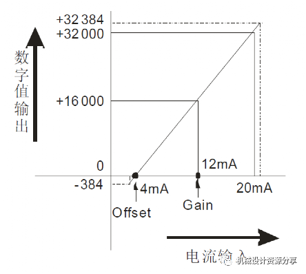
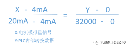
The above shows the relationship between Delta PLC current input signals and read signals.
Through the above relationship diagram, it can be seen that for any current input signal (X), and the read numerical signal (Y), there is the following corresponding relationship:
By transforming the above formula, we can obtain the following direct conversion formula:
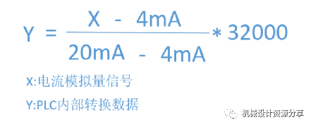
From the above formula, the integer data read by the PLC can be converted into the analog current signal value received by the PLC.
2. The conversion between actual physical values and analog data
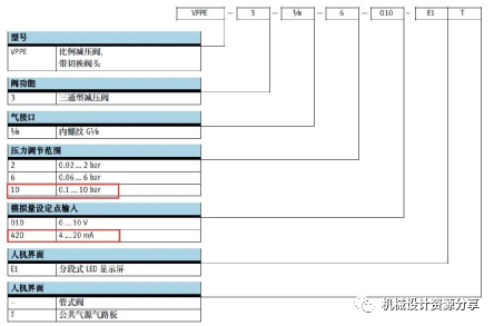
The conversion between actual physical values and analog data is the same as the conversion method above. Below is the conversion relationship formula for a pressure transmitter’s pressure and analog signal range (0.1-10bar, 4-20mA); similarly, the pressure and current have the following conversion relationship formula:
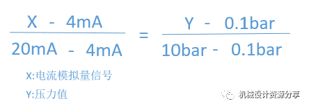
By transforming the above formula, we can obtain the following direct conversion formula:
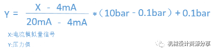
From the above formula, we can directly convert the analog current signal into pressure value data.
3. The direct conversion between actual physical values and PLC internal data
To convert the data read by the PLC into actual physical values, the above two steps of conversion can be used. When processing, skipping the conversion of input signal value size can yield the following relationship:
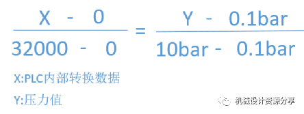
By transforming the above formula, we can obtain the following direct conversion formula:
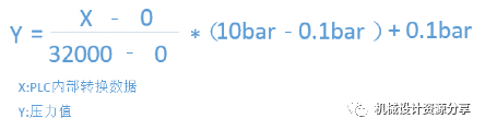
Through this formula, we can directly convert the data read by the PLC into actual physical values.
The above is the processing process and methods of PLC for analog signals.
Disclaimer: This article is a network reprint or adaptation, and the original author could not be found. Copyright belongs to the original author. If there are any copyright issues, please contact for deletion.
My Mechanical Network: www.mejxw.com
Free sharing of various mechanical design resources
Welcome everyone to join