To join the hardware electronics learning group, reply with “Join Group“.
Sometimes, when a circuit needs to implement a master-slave communication setup, the commonly used communication protocols are SPI, I2C, or RS485 bus forms. Among these, I2C is the simplest and most convenient for on-board communication, requiring only two wires to establish a bus.
However, due to certain reasons, we may need to consider another design, which is to enable the serial port to implement a master-slave bus design. For example, if the main MCU on the board has only one serial port but wants to communicate with two other MCUs using this single port. We know that conventional serial ports can only send one-to-one, meaning the master RX connects to the slave TX, and the master TX connects to the slave RX for communication. So how can we achieve a master-slave setup with one master and multiple slaves?
Circuit Implementation:
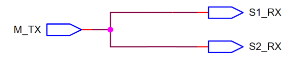
The master TX can be connected to multiple slave RXs simultaneously, meaning the master sends information in a broadcast manner, and each slave can receive the information sent by the master (the sent information must include the slave’s information so that the slave knows whether the master intends to communicate with it).
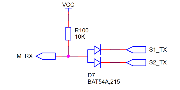
Since the idle state of the serial port is high, and low state represents data/start bit, the slave can send data by using diodes to build an AND gate, allowing the TXs of two slaves to perform logical AND operations. Thus, when slave 1 sends data, slave 2 remains idle (outputting 1), ensuring that slave 2 does not interfere with the data being sent by slave 1.
 Similarly, integrated logic gates, such as the SGM7SZ08 dual-input AND gate, can also achieve the same effect. The circuit diagram is as follows:
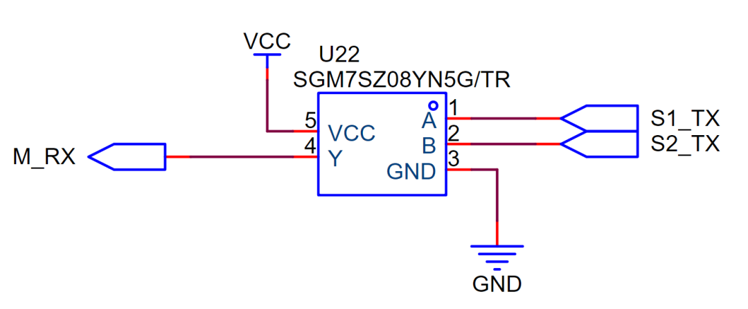 What do you think of this circuit? Feel free to leave your comments and share your thoughts.Thank you for reading, sharing, and liking!
 To join the hardware electronics learning group, reply with “Join Group“.Recommended Reading▼
-
Analysis of Bidirectional Constant Current Source Circuit
- Wiring Diagram Design for 4~20mA Loop Temperature Transmitter
- Non-Isolated 40-400V High-End Current Detection Solution Sharing
-
Can You Get 15K with This Written Test Answer?
-
Push-Pull Output and Emitter Follower: The Intricate Connections
Share, like, and enjoy ❤