During the process of vulnerability exploitation for smart devices, firmware extraction is the first step in analysis and the first step towards success.
In previous analyses, the firmware was stored in TSOP8 package NOR flash, which could be extracted directly using a chip clip or by soldering the flash chip for extraction, followed by using binwalk to obtain the entire file system. However, for recently analyzed devices, the firmware is stored in TSOP48 package NAND flash, which does not have a corresponding chip clip and requires a certain level of soldering skills. Additionally, due to the characteristics of NAND flash storage (such as OOB data interference), even if physical extraction is successful, subsequent data processing can be quite complex.
Next, I will share a method I have explored and summarized for extracting firmware using UART debugging during the NAND flash firmware extraction process, combined with recent experiments. Due to my limited abilities, I welcome corrections from experienced individuals.
UART debugging allows access to the Linux system command line.
MTD (Memory Technology Device) is a Linux subsystem used for accessing storage devices (ROM, flash).
By checking the partition information of MTD devices through the /proc file system, it can be found that mtdN and mtdblockN describe the same MTD partition corresponding to the same hardware partition. The two are different descriptions of the same MTD partition: mtdN is the character device corresponding to the MTD partition, while mtdblockN is the block device generated accordingly. Their contents are consistent, but the specific ioctl command operations are different.
Due to confidentiality, I will not disclose the specific model. Through a brief analysis and inspection of the silk screen, it can be determined that the firmware is stored in the flash indicated by the red box, as shown in the following image.
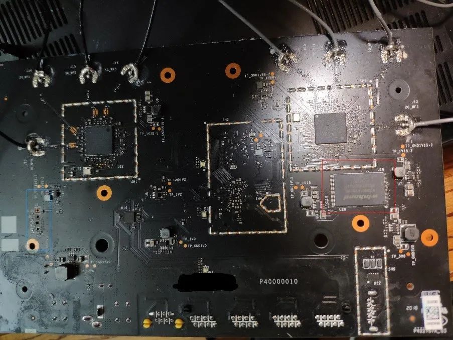
Fortunately, the circuit board has left a UART debugging port, and the attributes of each interface (GND, RX, TX, etc.) are labeled. Next, we can connect UART for debugging operations.
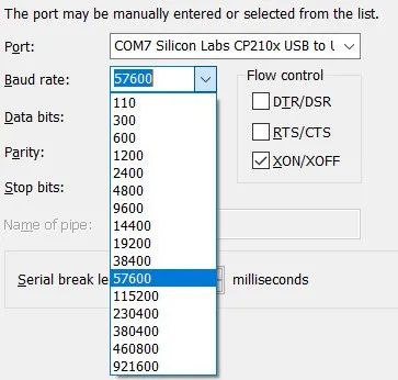
After connecting, I used SecureCRT to communicate with it. I selected the correct COM port and baud rate (baud rate testing generally starts from 9600, and you can refer to the common baud rates provided by SecureCRT for testing, as shown in the following image). When the interface has output and displays normal characters, the connection is correct.
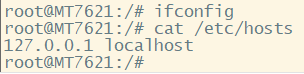
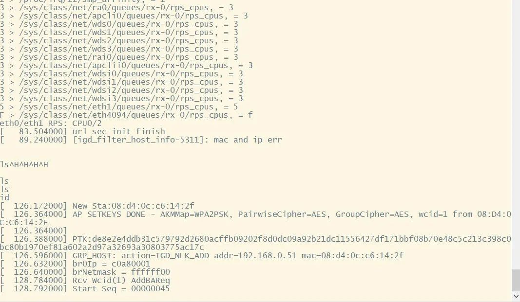
However, it is worth noting that after the system successfully starts, the UART debugging shell is closed, and at this point, only the system log output can be seen, and commands cannot be input to operate it, as shown in the following image.
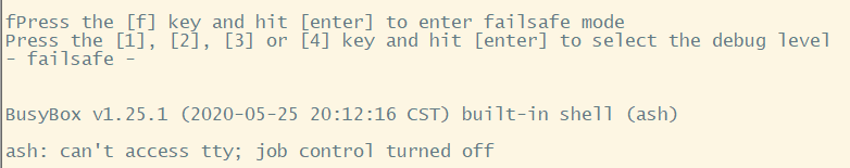
By carefully observing the entire boot process of the device, we find that during the bootloader startup, it provides us with an opportunity to enter the system, namely by pressing ‘f’ at a certain moment to enter failsafe mode. In this mode, we can access the Linux shell and input commands, allowing us to “see” the entire file system of the device, as shown in the following image.
However, since the device has not fully started successfully at this point, it is disconnected from the outside world and cannot communicate with it. This clearly does not help us analyze effectively. Therefore, how to export the entire file system while disconnected from the network is the next problem to solve.
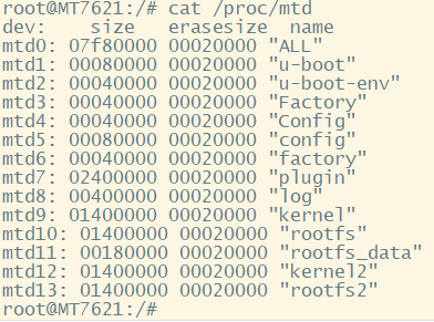
By checking /proc/mtd, we can obtain the basic information description of each MTD partition. Among them, mtd10, mtd11, and mtd13 may be the file systems we need to analyze, as shown in the following image.
At this point, since the interaction with the device can only remain at the command line echo, a clever method is to convert the contents of the corresponding MTD partition into visible characters (such as hexdump, base64). By recording the command line output echo, we can obtain the entire file system. However, it should be noted that due to the large amount of content in the MTD partition and the limited processing performance of embedded devices, it can only be recorded in segments by combining SecureCRT scripting.
The key code is as follows:
def send_cmd(fp,offset,step):     crt.Screen.Synchronous = True  # Send the initial command then throw out the first linefeed that we see by waiting for it.         crt.Screen.Send("hexdump {} -s {} -n {}
".format("/dev/mtdN",offset,step))      crt.Screen.WaitForString("\n")        # Create an array of strings to wait for.      promptStr = "root"       waitStrs = ["\n", promptStr]        row = 1       while True:          # Wait for the linefeed at the end of each line, or the shell          # prompt that indicates we're done.          result = crt.Screen.WaitForStrings( waitStrs )           # If we saw the prompt, we're done.          if result == 2:              break          # The result was 1 (we got a linefeed, indicating that we          # received another line of output). Fetch current row number          # of the cursor and read the first 20 characters from the screen          # on that row.           #           # This shows how the 'Get' function can be used to read          # line-oriented output from a command, Subtract 1 from the          # currentRow to since the linefeed moved currentRow down by one.          #            screenrow = crt.Screen.CurrentRow - 1          readline = crt.Screen.Get(screenrow, 1, screenrow, 48)          readline = readline.strip()                  # NOTE: We read 48 characters from the screen 'readline' may          # contain trailing whitespace if the data was less than 48          # characters wide.           # Write the line out with an appended end-of-line sequence          fp.write(readline)             crt.Screen.Synchronous = False
Offset and step correspond to the hexdump offset and the number of bytes displayed, which can be set according to actual needs.
This article summarizes a method for obtaining the file system of a device using UART debugging, which is key to converting invisible characters into terminal-visible characters using hexdump or base64.
The main limitation of this method is that the circuit board must have a UART debugging port and the device must have related conversion commands (although hexdump is a very basic command).
1. https://bbs.pediy.com/thread-230095.htm
2. https://zhuanlan.zhihu.com/p/26745577
Original source: ChaMd5 Security Team