How to Build a High-Performance Mini Desktop Scroll Saw
DIY a High-Performance Mini Desktop Scroll Saw
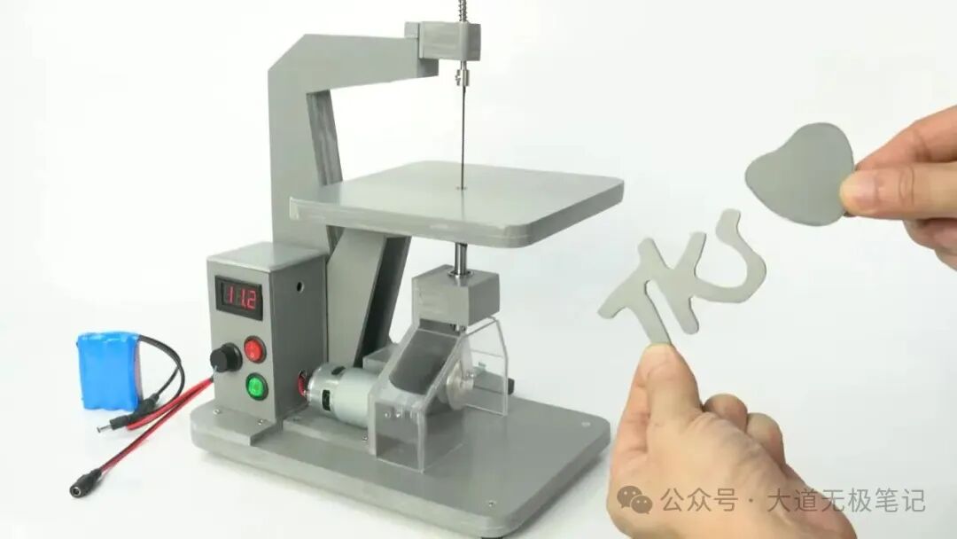
Product Features Overview
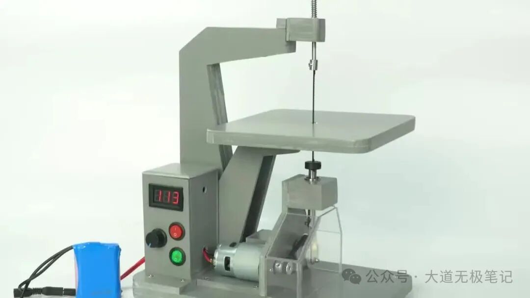
Compact Structure, Portable & Easy to Use
Infinitely Adjustable Speed
PWM Speed Control Module: Current 10A, Voltage 12-40V
Suitable for Precision Cutting of Thin Sheet Materials
Blade Specifications: 18T, Length 133mm, Width 3mm
DC Motor Driven
Motor Model: 775 Motor, Voltage 12-24V, Speed 2500-20000rpm
Multiple Power Supply Options
Compatible with Battery Packs or DC Power Adapters (demonstration uses 18V 5A power supply)
Compact Dimensions
Height approximately 32cm, Worktable size approximately 18cm x 24cm
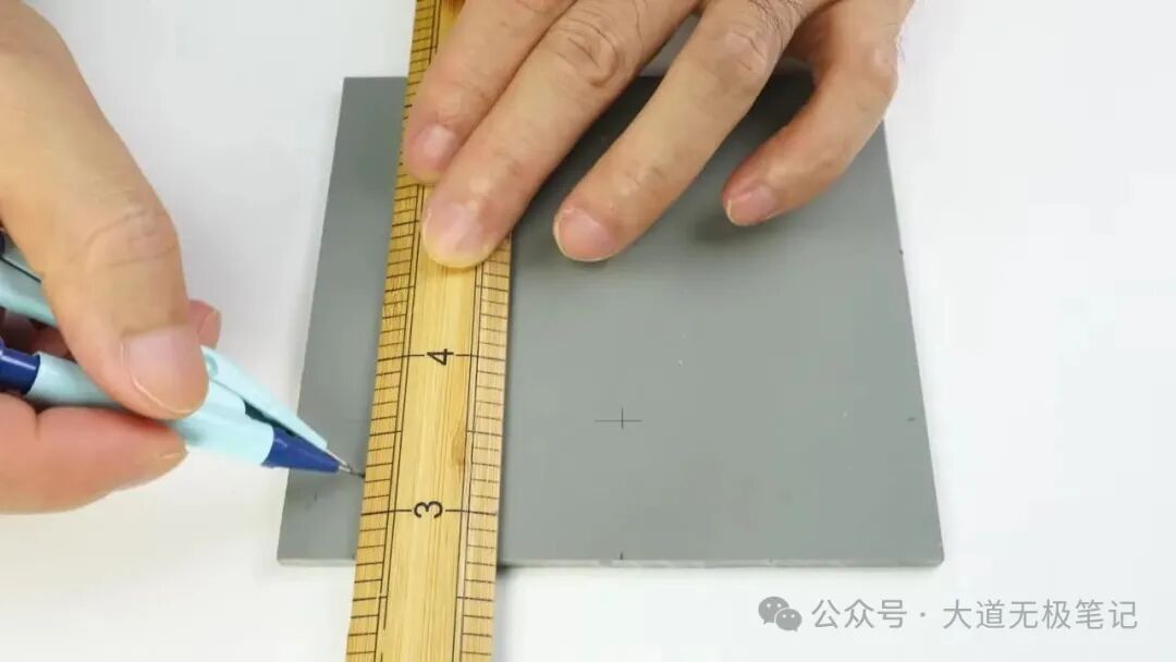
Step 1: Prepare Base Plates for Drive Mechanism
Mark cutting lines on plastic sheets. Cut pieces to required size.
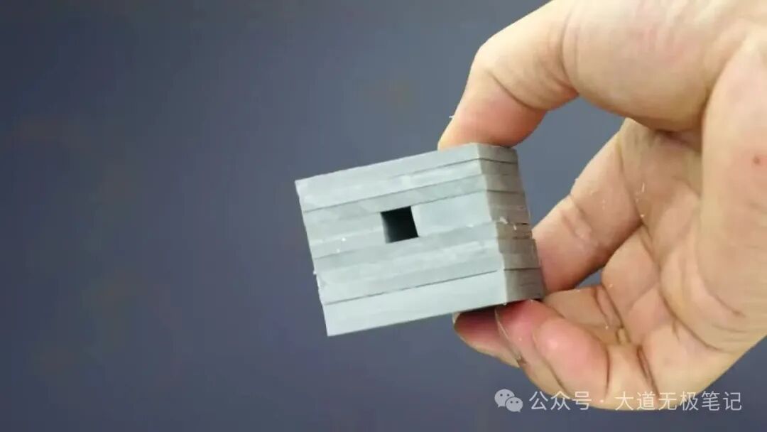
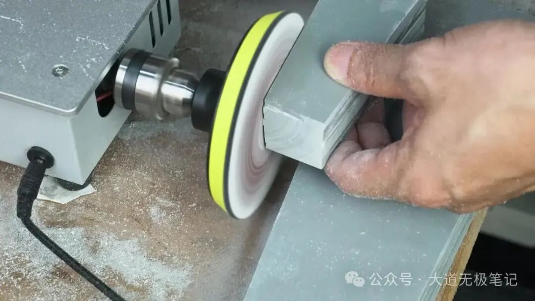
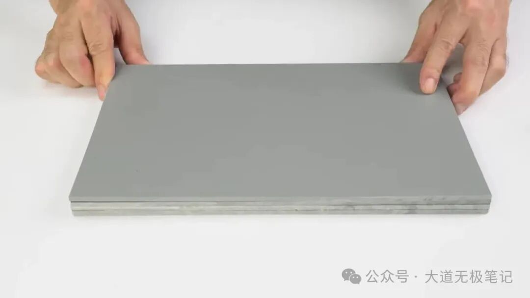
Bond multiple layers for thickness and sand the surface.

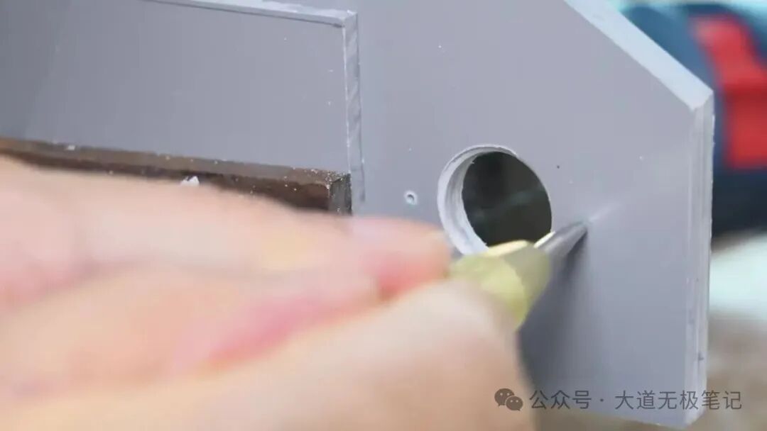
Step 2: Fabricate Motor Mount and Install Bearing
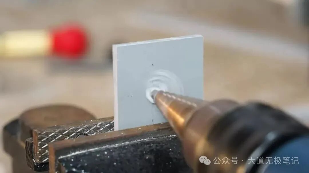
Mark and drill holes on the bonded piece for motor and bearing installation. Install an axle bearing (Inner diameter: 5mm, Outer diameter: 10mm).
Step 3: Fabricate and Install Large Pulley Bearing Block
Bond multiple layers to make a square bearing block, drill a hole and install a linear bearing (Inner diameter: 10mm, Outer diameter: 19mm).
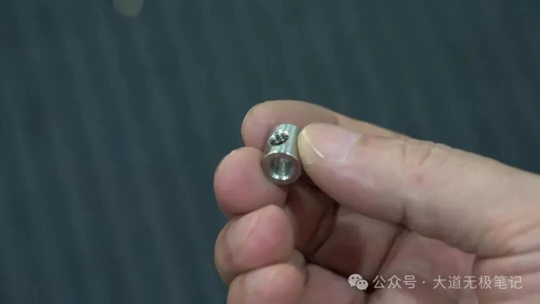
Step 4: Fabricate Connecting Rod
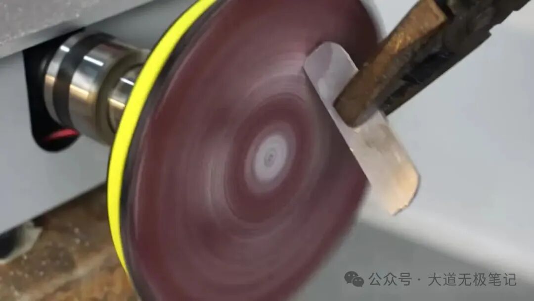
Cut and sand aluminum square tube.
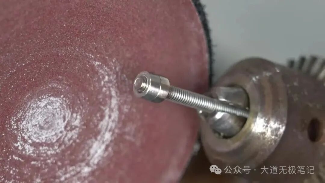
Drill holes at both ends of the connecting rod, install a bushing at one end.
Bushing Inner diameter: 5mm, Outer diameter: 10mm
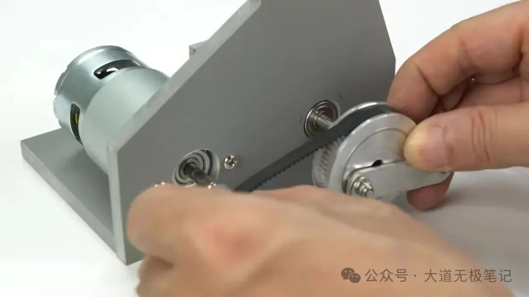
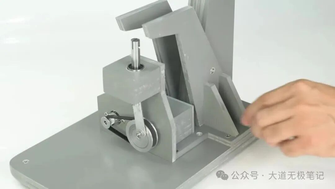
Step 5: Install Synchronous Pulleys and Connecting Rod
Drill a hole on the large synchronous belt pulley (60 teeth) for a screw. Fix the small synchronous belt pulley (20 teeth) onto the motor shaft. Fix the connecting rod to the large synchronous belt pulley with a screw.

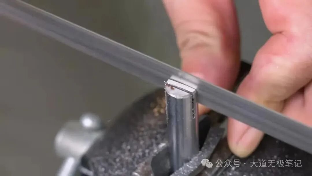
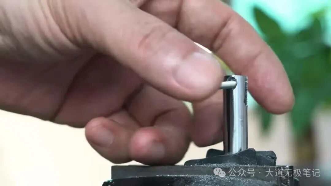
Step 6: Fabricate Vertical Shaft Holder Tube
Cut and sand metal tube. Make a slot on the tube and drill a hole for a pin.
Step 7: Fabricate Upper Saw Blade Clamp
Fabricate a metal clamp part to hold the upper end of the saw blade.
Step 8: Fabricate Main Body Frame
Cut and bond multiple layers of plastic sheets to form the “C”-shaped frame.
Step 9: Fix Drive Mechanism to Base and Frame
Fix the motor/drive mechanism base onto the main frame base. Secure connections with screws.
Step 10: Fabricate and Install Work Table
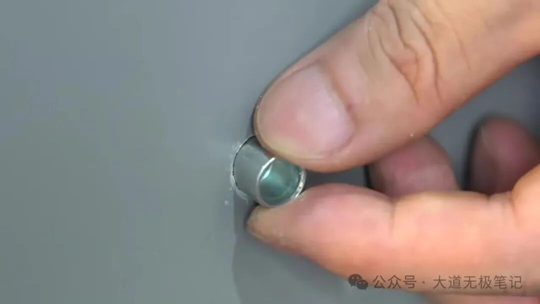
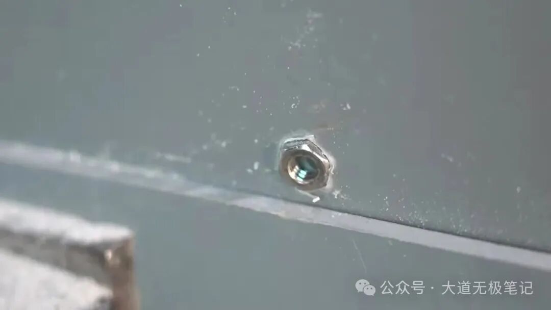
Bond multiple layers for the work table, trim and sand edges. Drill a hole in the center for the saw blade and install a bushing/insert.
Step 11: Fix Work Table to Base
Drill holes on the base, install bushings, then fix the work table to the base with screws. Install rubber feet.

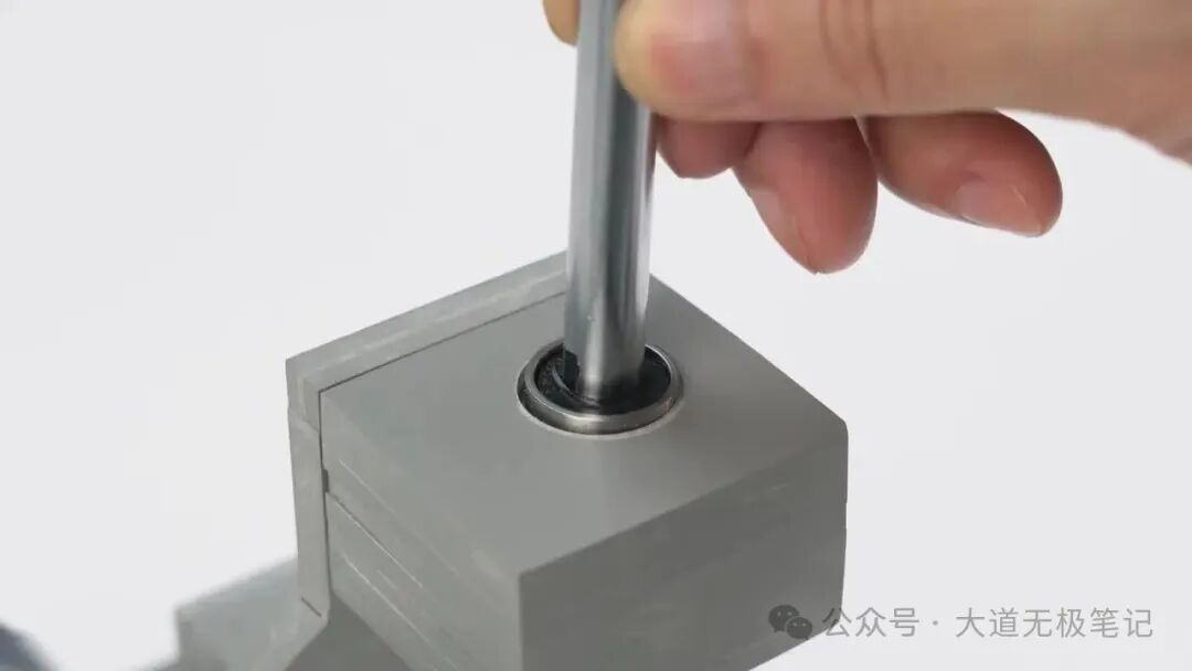
Step 12: Install Vertical Shaft and Saw Blade Mechanism
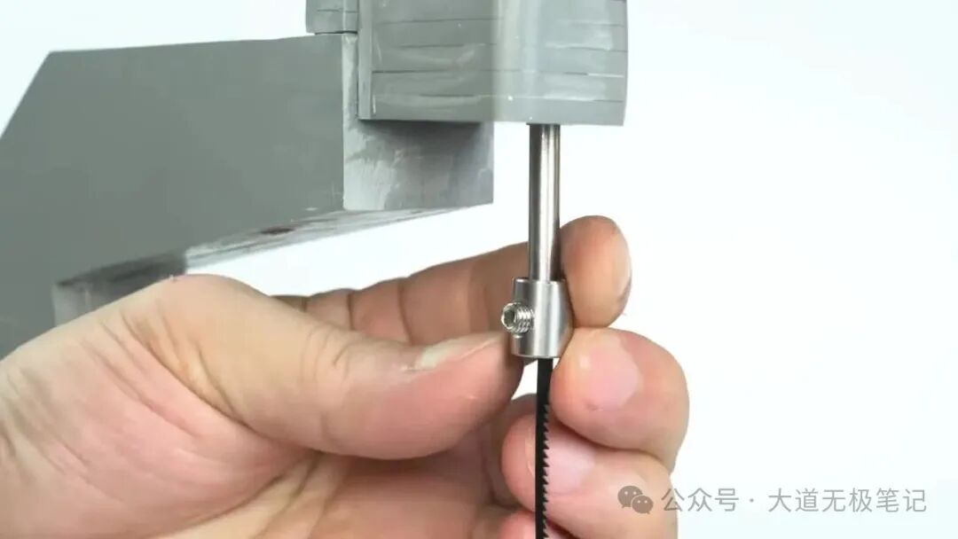
Insert the vertical shaft through the upper and lower bearing blocks, connect the connecting rod. Install the upper saw blade clamp and spring, adjust the blade tension.
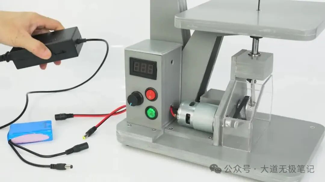
Step 13: Fabricate and Install Control Box
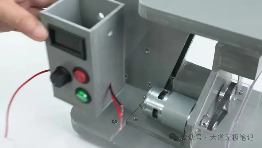
Fabricate the control box enclosure, install and wire the PWM Speed Regulation Switch (Current: 10A, Voltage: 12-40V), voltage display, switches, and terminals.

Step 14: Final Assembly and Power Connection
Fix the control box to the machine body, connect motor wires and power connectors. Can be powered by a battery pack or 18V 5A DC power adapter.
Step 15: Cutting Demonstration
Turn on power, adjust speed, and perform precise cutting operations.

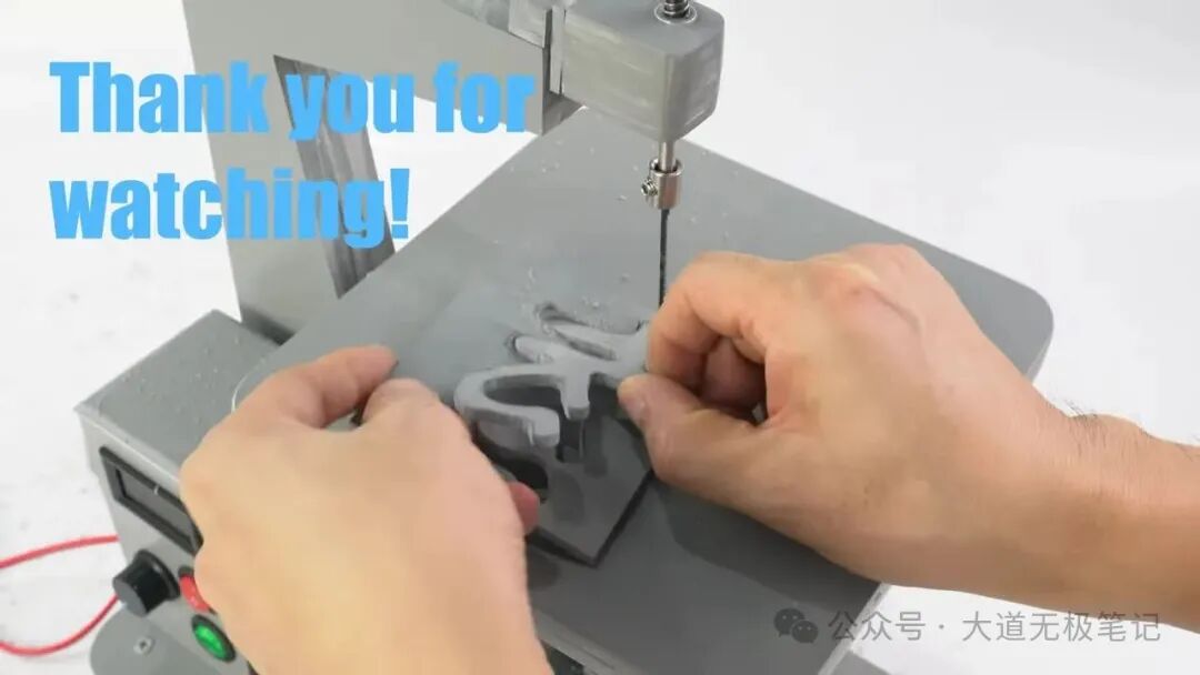
Thank you for watching!
Thank you for watching!