01
Overview
1.1 Introduction
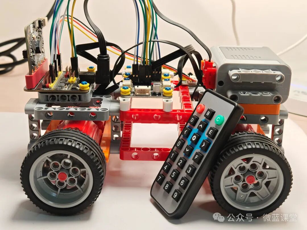
Today, I will share a case of a remote-controlled four-wheel drive car. Compared to other cars:
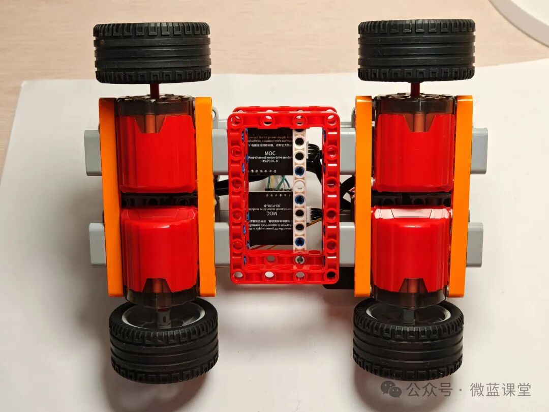
- It has motors directly connected to the wheels, so it has a simple structure and is easy to assemble;
- It is very sturdy, and even if it flips over, there is no need to readjust the equipment;
- The chassis is flat, suitable for adding ultrasonic obstacle avoidance, line-following, and other sensors.
1.2 Course Objectives
- [Scientific Knowledge] Understand the differences between front-wheel drive, rear-wheel drive, and four-wheel drive.
- [Programming Knowledge] Master how to abstract real-life cases using functions.
- [Hardware Knowledge] Master the use of motor drivers.
- [English Knowledge] wheel: tire; left: left side; right: right side; front: front; rear: back; forward: move forward; retreat: move backward.
02
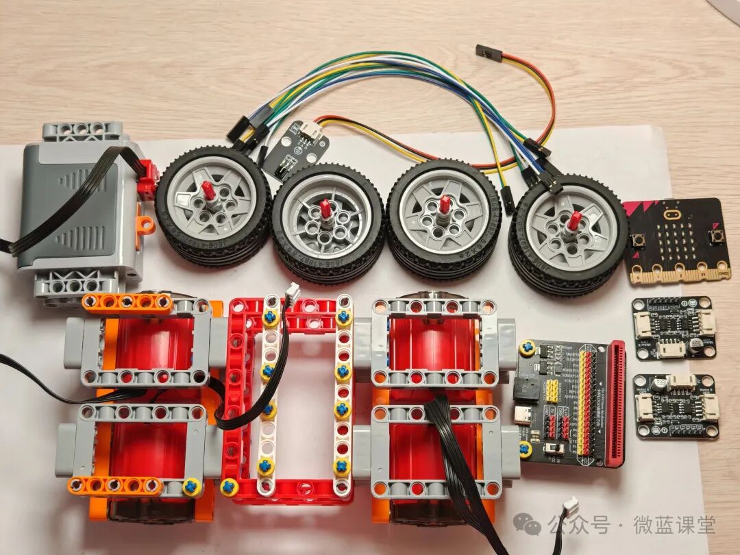
Parts List
|
Small particle building blocks |
Several |
|
micro:bit main board |
x 1 |
|
micro:bit expansion board |
x 1 |
|
Dual motor driver module |
x 2 |
|
LEGO XL motor |
x 4 |
|
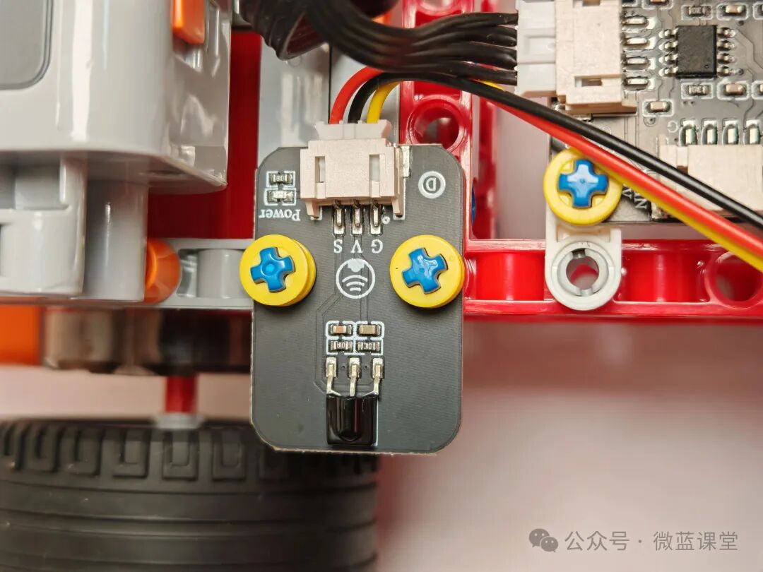
38K infrared remote control receiver module |
x 1 |
|
38K infrared remote control |
x 1 |
|
5V power box |
x 1 |
|
Power cable |
x 1 |
|
2P Dupont wire |
x 6 |
03
Assembly Process
04
Program Explanation
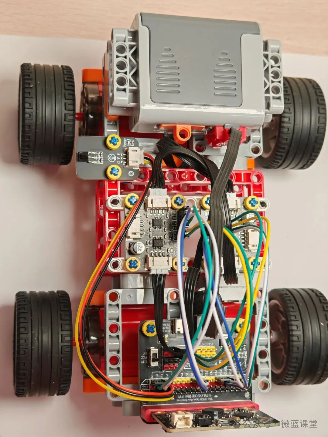
4.1 Wiring
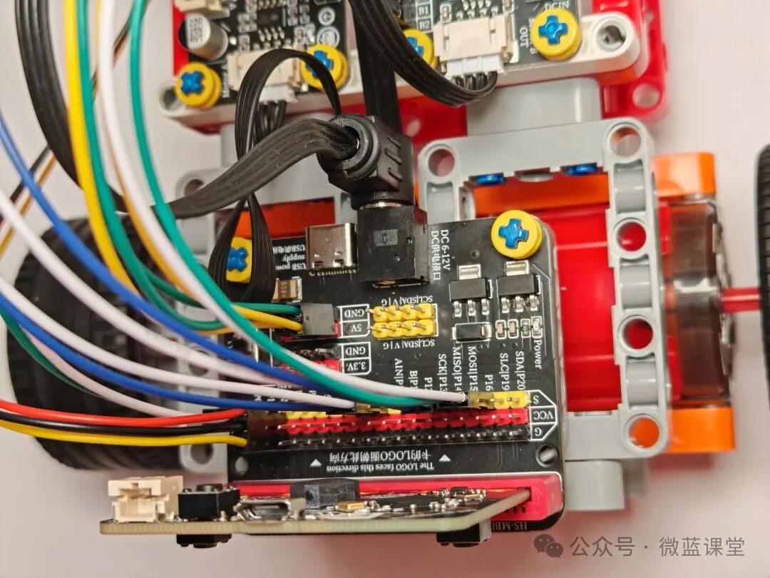
- LEGO power cable: one end is a LEGO quick connector, connected to the power box; the other end is a DC head, plugged into the DC port of the expansion board.
- 38K infrared remote control receiver module: PH2.0 end connected to the 38K infrared receiver module, Dupont end connected to the expansion board’s P2 row pin, note that the S signal line must be inserted into the S pin of the P2 row.
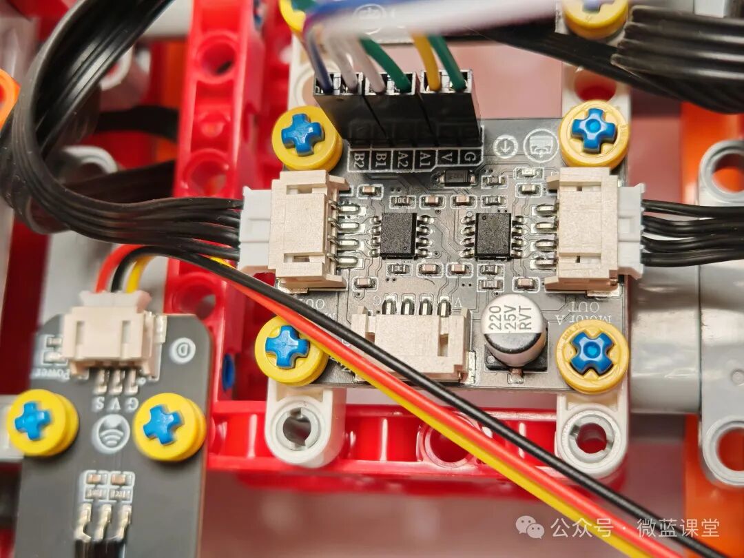
- Two red-black 2P Dupont wires: one end connected to the expansion board power, red to 5V, black to GND; the other end connected to the motor driver module, black to G, red to V.
- Four motor plugs: inserted into the Motor interface of the motor driver module.
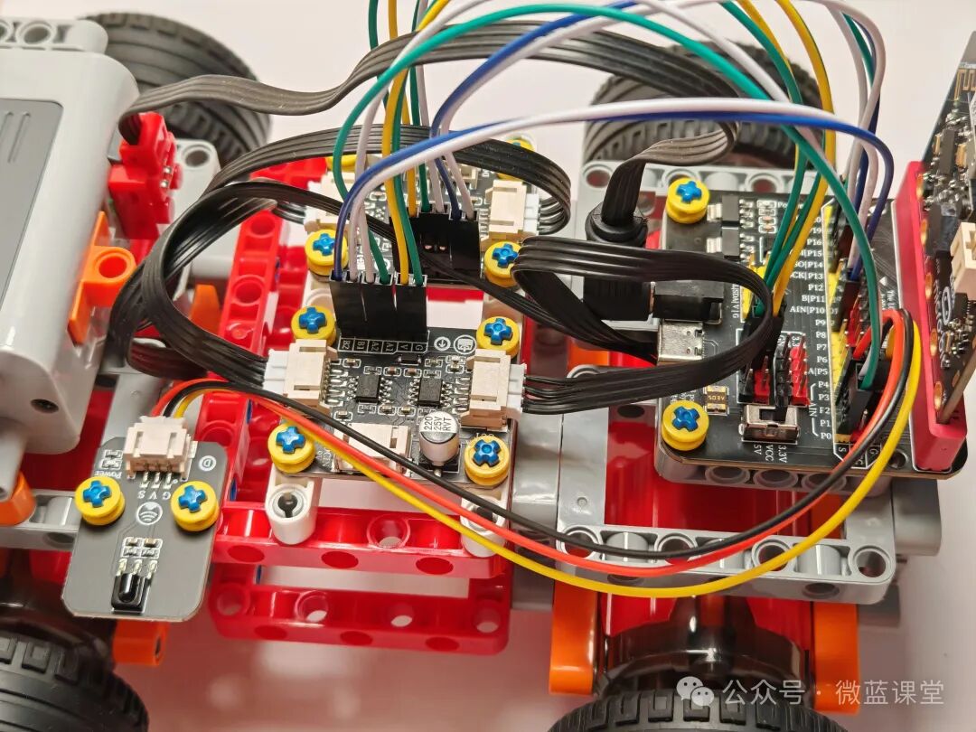
- Four 2P Dupont wires: one end connected to the various AB pins of the motor driver module, the other end connected to the expansion board pins.
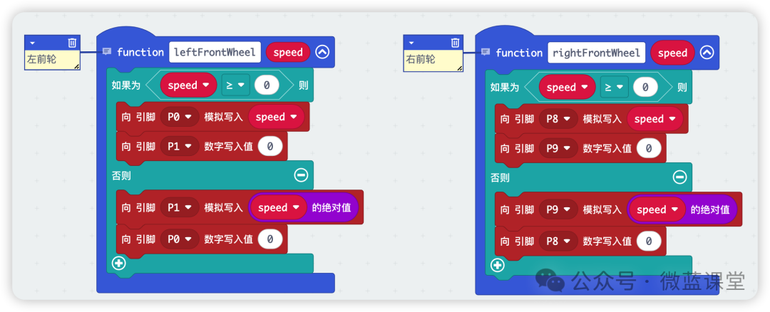
- Left front wheel connected to the right motor driver’s A1A2, corresponding to P0P1;
- Right front wheel connected to the right motor driver’s B1B2, corresponding to P8P9;
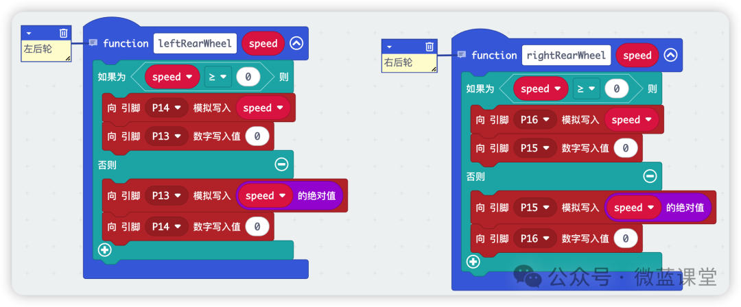
- Left rear wheel connected to the left motor driver’s A1A2, corresponding to P13P14;
- Right rear wheel connected to the left motor driver’s B1B2, corresponding to P15P16.
4.2 Program
Program sharing: https://makecode.microbit.org/_haKdTU6eWUhE
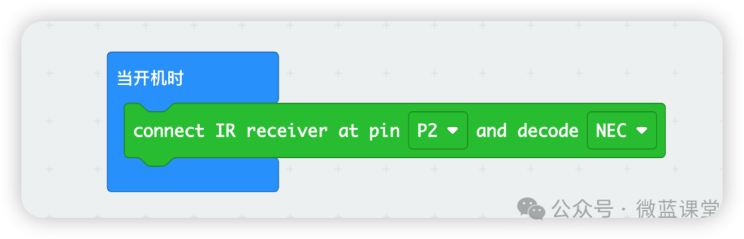
Program Explanation:
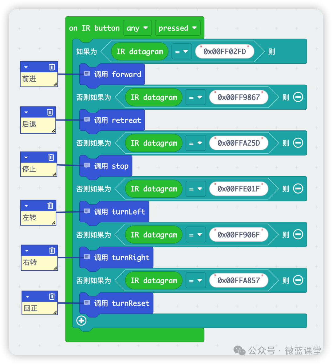
When powered on, set the P2 port to receive infrared remote control signals.
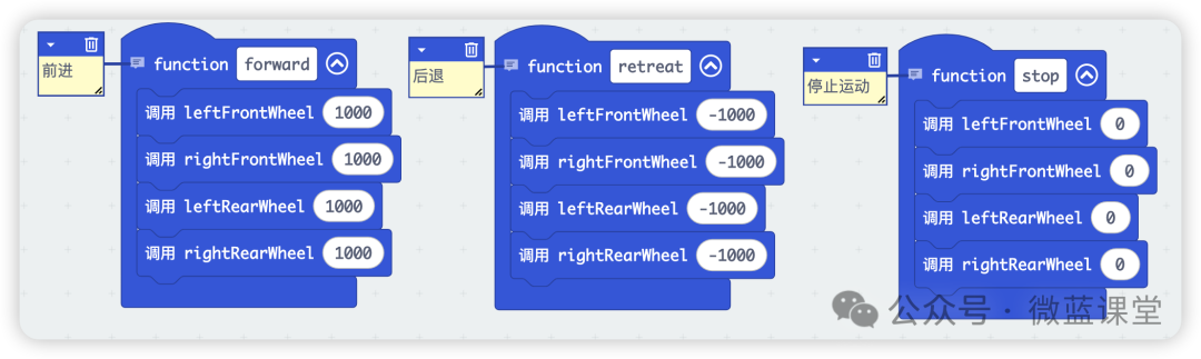
Create two functions for controlling the left front wheel and the right front wheel.
Create two functions for controlling the left rear wheel and the right rear wheel.
Create three functions to control the car’s forward, backward, and stop movements.
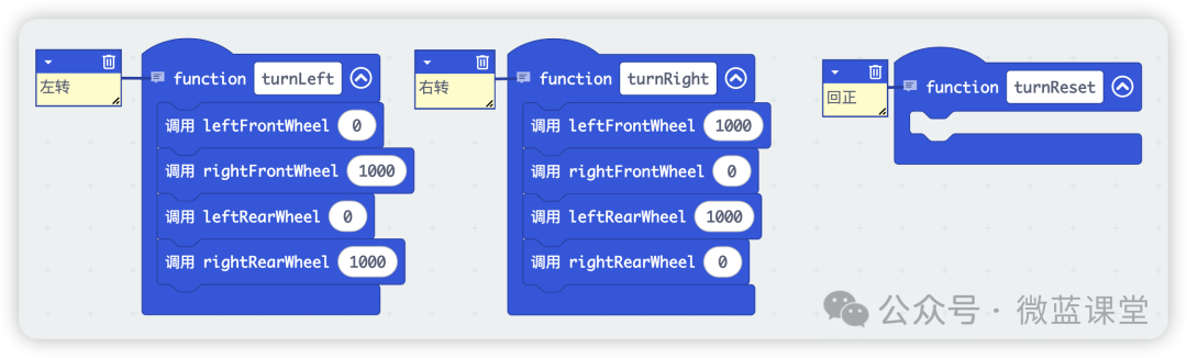
Create two functions to control the car’s left and right turns.
Receive signals from the remote control button and process accordingly.
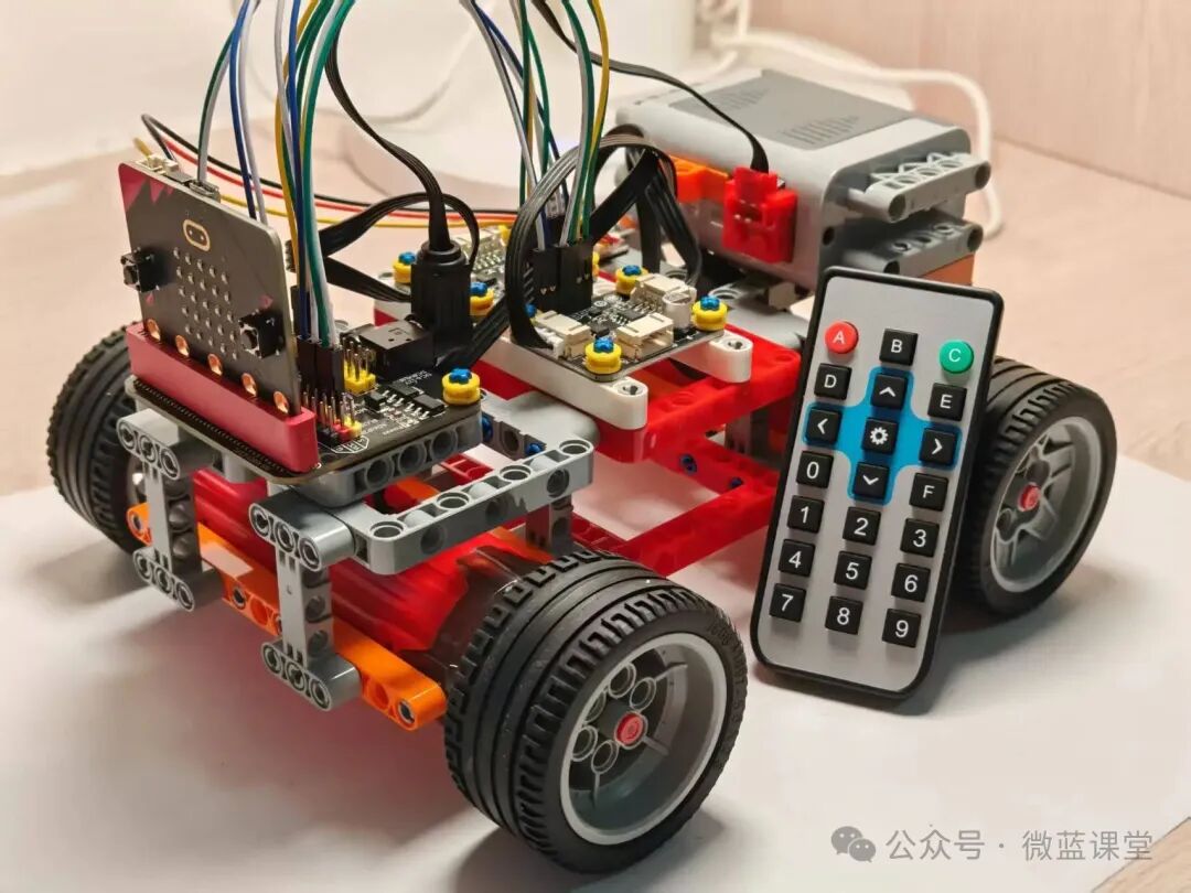
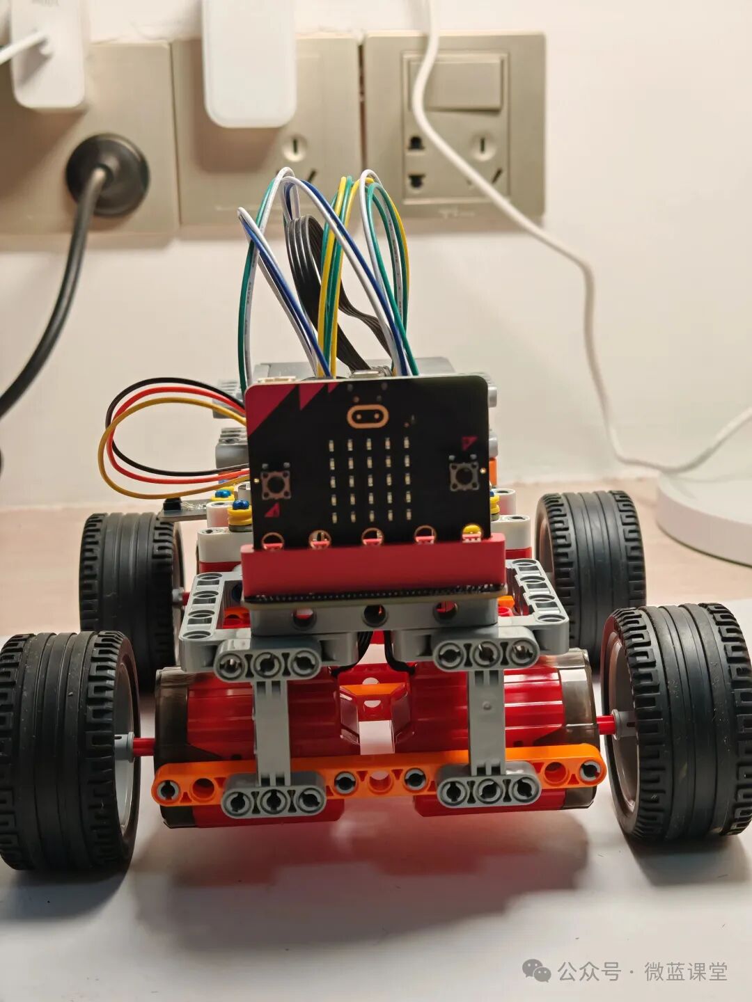
05
Product Display
Students who need accessories can purchase them from my Taobao store with the same name.
 Follow me for more sharing|Weilan Classroom