 Received feedback from many readers: “Clearly following the tutorial, but the STM32 board’s LED won’t light up?” This phenomenon hides hardware differences in embedded development that are easily overlooked, the connection method of the onboard LED and GPIO pins, is the most common “pitfall” for beginners transitioning from Arduino to STM32. Every line of code is a relay baton of technical inheritance!
Comparison of STM32 and Arduino Development Boards
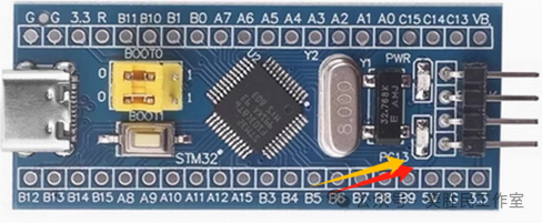 STM32 Core Board
 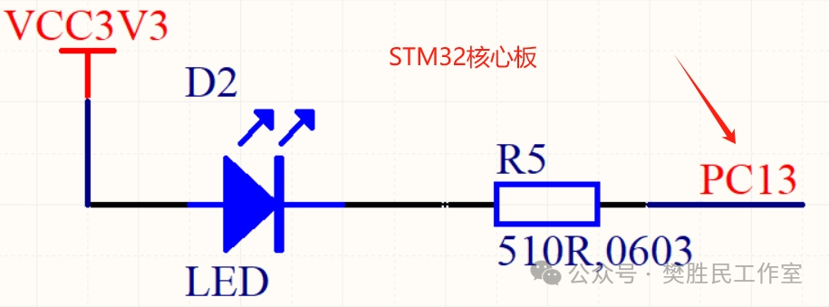 Onboard LED of STM32 Core Board, corresponding LED circuit (LED negative connected to IO through a series resistor)
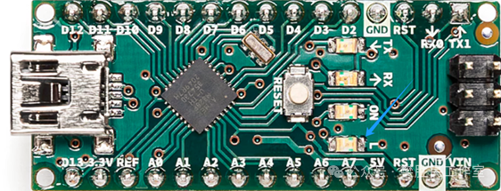
Arduino Nano
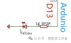
Onboard LED of Arduino Nano, corresponding LED circuit (LED positive connected to IO through a series resistor)
Summary:
In the STM32 minimal system development board (such as STM32F103C8T6), the PC13 pin is commonly used to drive the LED indicator, and is usually designed for low-level driving mode, meaning that when PC13 outputs a low level, the LED lights up, and when it outputs a high level, it turns off. Therefore, the negative of the LED is connected to the PC13 pin, and the positive is connected to the power supply (such as 3.3V) through a current-limiting resistor.
In contrast, in the Arduino Nano, the D13 pin is typically connected to the positive of the onboard LED, while the negative is connected to GND through a current-limiting resistor. Thus, when the D13 pin outputs a high level, the LED lights up; when it outputs a low level, the LED turns off.
STM32 Core Board LED Lighting Simplified Program
#include “stm32f10x.h” // Include standard peripheral library header file
int main(void)
{
// 1. Enable GPIOC clock
RCC_APB2PeriphClockCmd(RCC_APB2Periph_GPIOC, ENABLE);
// 2. Configure PC13 as push-pull output mode
GPIO_InitTypeDef GPIO_InitStructure;
GPIO_InitStructure.GPIO_Pin = GPIO_Pin_13;
GPIO_InitStructure.GPIO_Mode = GPIO_Mode_Out_PP; // Push-pull output
GPIO_InitStructure.GPIO_Speed = GPIO_Speed_50MHz; // Low-speed mode
GPIO_Init(GPIOC, &GPIO_InitStructure);
// 3. Light up LED (PC13 outputs low level)
GPIO_ResetBits(GPIOC, GPIO_Pin_13);
while (1) {
// Main loop remains empty, LED stays lit
}
}
Arduino Nano LED Lighting Simplified Program
#define LED_PIN 13void setup( ) {
//InitializeLED_PIN as output mode
pinMode(LED_PIN, OUTPUT);
// SetLED_PIN to high level, LED lights up
digitalWrite(LED_PIN, HIGH);
}
void loop() {
// Main loop remains empty, LED stays lit
}