In modern AI data centers and edge computing environments, high power density and integration are mandatory requirements. To meet the demand for efficient power management solutions, Microchip Technology has launched the MCPF1412 power module, a highly integrated Point of Load (POL) buck converter featuring I2C and PMBus® interfaces, compact size, system telemetry, and protection functions, all encapsulated in a small form factor with good thermal performance.
Main Features of MCPF1412
The MCPF1412 is an integrated, high-efficiency DC/DC regulator that can provide up to 12A of output current and an output voltage of 0.6–1.8V to the load point via a 16V bus in a Buck Converter configuration. The block diagram of the power module shown in Figure 1 exhibits high integration, including logic, control, and power module (gate drive and driver/power stage). The IC also includes passive components such as capacitors and inductors.
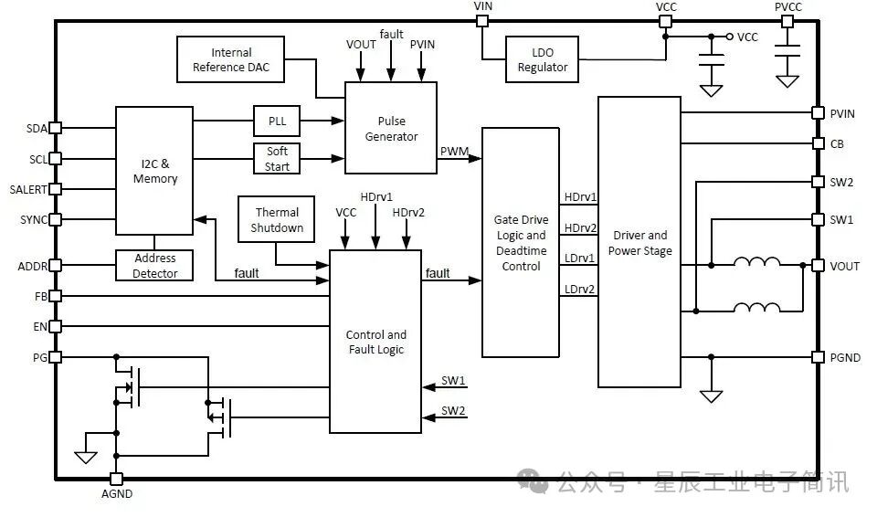
Figure 1: Block diagram of the MCPF1412 power module (Source: Microchip Technology)
The main technical features of the MCPF1412 are as follows:
-
POL module with output inductor
-
Small size: 5.8mm x 4.9mm x 1.6mm
-
Continuous 12A load capability
-
Wide input voltage range: 4.5-16V
-
Adjustable output voltage: 0.6-1.8V
-
No external compensation required
-
Programmable features using I2C and PMBus™
-
Enable input, programmable under-voltage lockout (UVLO) circuit
-
Power good indicator
-
Built-in protection features
-
Operating temperature from -40°C to +125°C
-
Lead-free and halogen-free
-
Compliant with EU REACH and RoHS standards
The MCPF1412 is supported by the EV37R94A evaluation board and accompanying GUI, providing developers with the tools needed to evaluate their designs.
Power Conversion
The Pulse Generator module produces pulse-width modulation (PWM) signals to drive integrated MOSFETs. To generate switching waveforms, this control module employs a proprietary modulation scheme that implements internal compensation. External compensation uses external components (typically capacitors, resistors, and inductors) to shape loop gain and phase, while internal compensation integrates these components into the control module, making the solution more compact and reducing the need for external components.
Microchip’s solution not only eliminates the need for external compensation but also provides a highly stable feedback control loop, ensuring that the power converter maintains a consistent output voltage during load or input voltage changes. Thus, the stability of the control loop ensures a fast transient response.
The MCPF1412 implements a two-phase interleaved buck converter topology. This design choice reduces voltage stress on internal power components, allowing for a more compact package. While achieving this size reduction, the switching losses are comparable to those observed in traditional interleaved buck converters with the same specifications. A key feature of this architecture is its inherent current sharing capability between the two phases.
Given that the MCPF1412 has the capability to operate independently, it employs Constant On-Time (COT) control. COT uses ripple feedback from the output voltage and internally provided synthetic ripple to provide inherently stable operation during line and load transients.
Communication Interface and Standalone Operation
The MCPF1412 is a flexible power module that provides I2C and PMBus interfaces for configuration and system monitoring. However, the device can operate in standalone configuration without a host controller, using an external resistor divider to set the output voltage and monitoring the health of the device through the Power Good output. By using a single resistor (the value of which is specified in Table 1), system designers can configure all system power outputs across the entire 0.6–1.8V output voltage range in standalone mode. As shown in Figure 1, the I2C and memory block can store configuration parameters in non-volatile EEPROM memory. This operation can be repeated a limited number of times.
The MCP1412 uses internal registers that can be programmed via I2C or PMBus standalone configuration, with factory-programmed default values persisting after power cycles. I2C/PMBus programming values revert to default after each power cycle unless they are written to non-volatile memory, which has a write cycle limit of 8.
Protection Features
The MCP1412 provides advanced protection and diagnostic features such as over-temperature (OTP), over-current (OCP), and over-voltage protection (OVP), ensuring optimal performance and enhancing device reliability. The device also integrates soft-start protection and thermal shutdown with automatic recovery features.
To prevent overheating, the device employs built-in over-temperature protection (OTP) at 145°C. If the internal temperature rises above this threshold, the device immediately stops switching all MOSFETs. Once the temperature drops below 145°C, it will automatically resume operation.
The over-temperature compensated over-current protection operates in hiccup mode. When the current exceeds the OCP threshold, the MCPF1412 enters hiccup mode. In this state, the MOSFET remains off during the hiccup blanking time. After this period expires, the MCPF1412 will attempt to restart. If the over-current condition persists, the hiccup procedure is repeated. Additionally, the MCPF1412 can be configured to activate latching shutdown mode upon detecting an over-current condition.
The device provides a status register accessible via the communication interface to understand the most critical faults detected during its operation. These faults include over-voltage, over-current, under-voltage, and over-temperature faults. When the MCPF1412 detects a fault condition, it alerts the MCU. The MCU can then initiate a polling cycle, and if the condition was triggered by hiccup, the internal registers of the MCPF1412 contain the information.
The integrated digital soft-start circuit in the MCPF1412 allows customization of the output voltage rise time and limits inrush current during startup. After power-up, the device exits reset mode, and its internal soft-start function gradually raises the output voltage to the set reference level. The acceleration rate is determined by settings in the internal configuration register.
During the initial phase of operation, the MCPF1412 limits the generation of high drive (HDrv) pulses until sufficient output voltage is detected. The MCPF1412 features an internal digital soft-start circuit designed to manage the output voltage rise time and limit inrush current during startup. The soft-start time can be programmed between 0 and 127.75 milliseconds. The soft-start time and the value of the output capacitor determine the magnitude of the inrush current.
Package
Thanks to its flat package, the MCPF1412 (Figure 2) is designed for efficient automated assembly using standard surface mount (SMT) components. This unique and optimized 12A POL solution currently offers the highest density functionality. The MCPF1412 features a thermally enhanced package design with a vertical structure to enhance thermal flow. This technology achieves the highest power density 12A design in its class, reducing circuit board space by up to 40%.
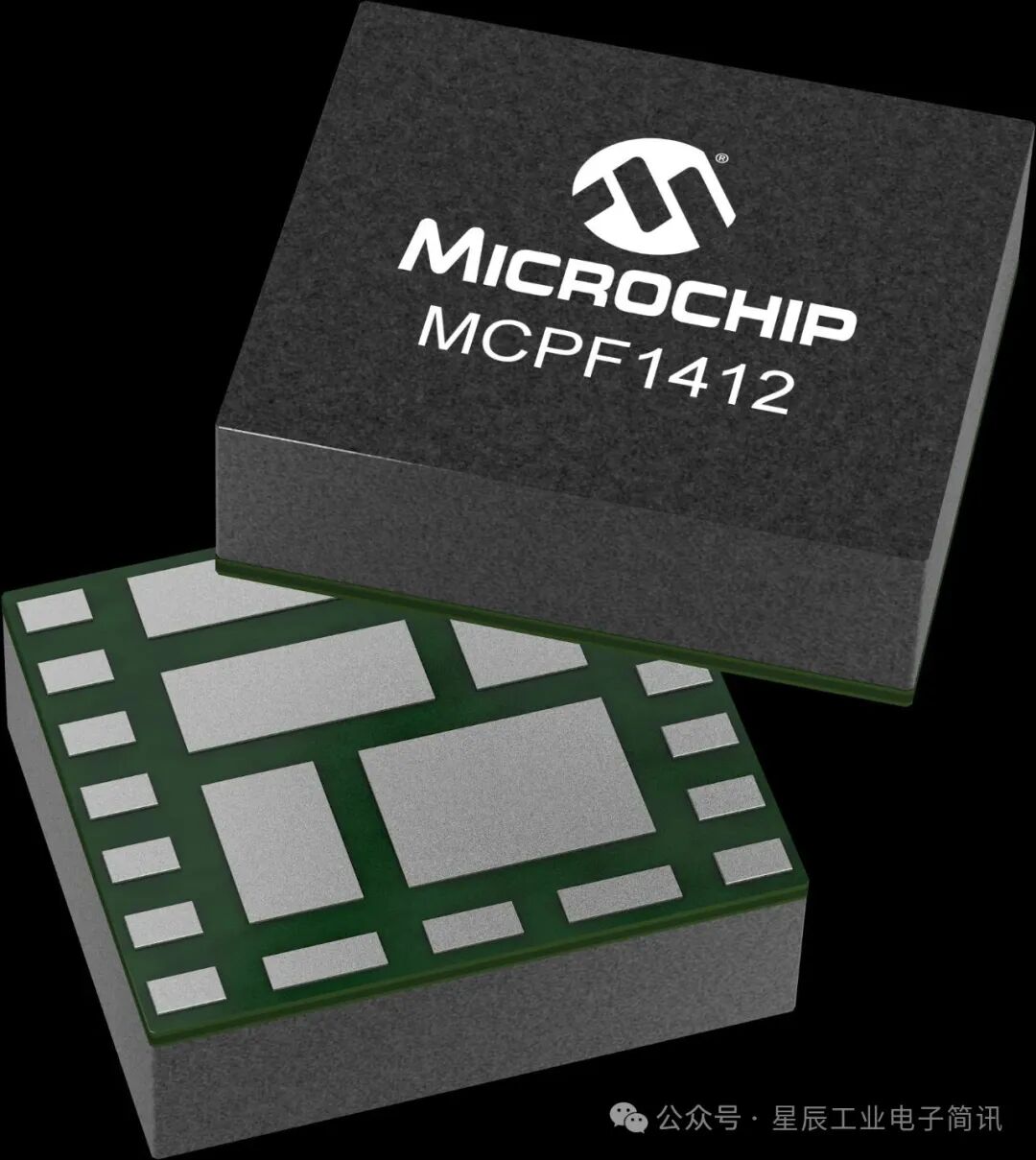
Figure 2: MCPF1412 in a 20-pin 5.8mm x 4.9mm Land Grid Array (LGA) package (Source: Microchip Technology)

This book systematically elaborates on the principles of pulse width modulation in DC-DC converters, DCM/CCM design methods, and stability analysis, including modeling, simulation, and experimentation, aiding in the realization of high-efficiency, low EMI, and fast transient response power systems.