
Project Name: Handcrafted 10G Soft Router NAS, using only LattePanda Mu PCIe board
Project Author: Mr. Light Up
Introduction
This is an extremely powerful expansion board!
It is equipped with 3 PCIe slots, supporting:
10G Network Cards
NVMe Expansion Cards
Graphics Cards, etc.
Various PCIe Devices
One board achieves network acceleration, storage expansion, and local AI computing!
Why do this?
When it comes to soft routers or NAS, most people probably think of those small black boxes with multiple network ports, or the impressively priced Synology.Many players would choose an All-in-One solution—one host to handle soft routing, NAS, streaming, etc.
But as an electronic engineer, I enjoy the joy of crafting a personalized solution after success.
Since that’s the case, let’s take on the challenge,and see if we can create a unique All-in-One hardware, perhaps using a 4-layer board, or even a 2-layer board, to do something different.
After some research, I found that it can indeed be done…
01Hardware Design”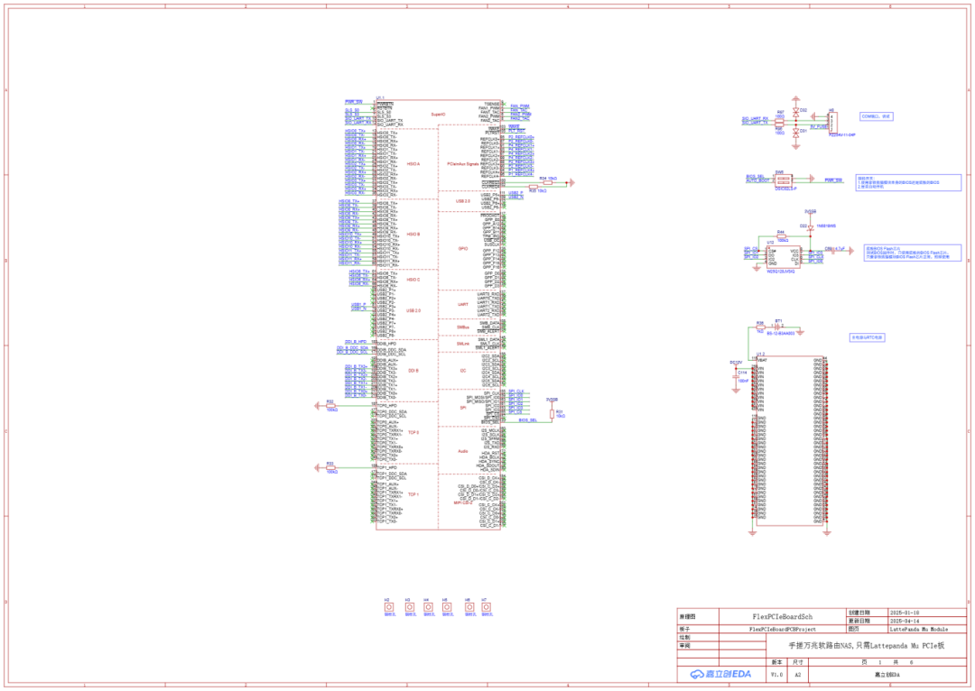
LattePanda Mu Module

Power
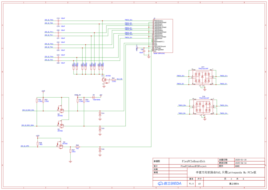
HDMI

USB
FAN
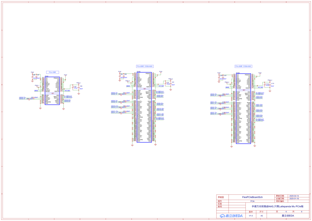
PCIe
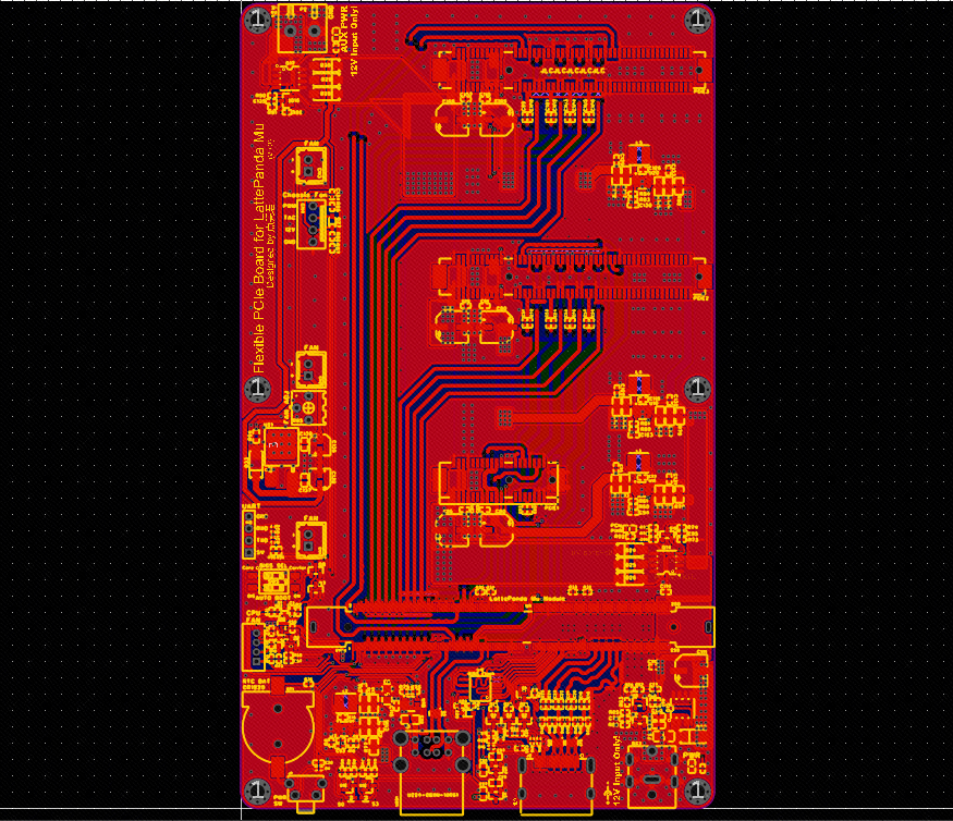
PCB Diagram
This section will share—selection criteria, routing techniques!
01 Selection Criteria(Network Card, Hard Drive, Motherboard)
1.1 Network Card Selection
Network card speeds vary; for ordinary home use, 1G and 2.5G are sufficient. In high-end fields, it gets even more exciting, with 10G, 25G, and even 40G, with optical ports achieving lightning-fast connections. It is worth mentioning that there are also electrical versions of 10G.
These are usually standard PCIe cards, such asthe INTEL X540-T2 dual-port 10G network card shown below, which has 2 onboard 10G electrical ports.

Although it is a server decommissioned product, it is cheap and durable (you can’t go wrong for 60 bucks)!
I mainly use it because I don’t have optical ports at home, only electrical ports, saving the hassle of buying optical modules.10G ports can theoretically run at 1GB/s, which is more than enough for internal file transfers; those who use it will say it’s great.
1.2 Hard Drive Selection
Mechanical Hard Drives for NAS?
Hey! The “da da da” sound of frying beans is annoying, especially with enterprise drives.
Now that SSD prices are getting closer to mechanical hard drives, why not go for a silent and high-speed SSD? Fast, noiseless, and quietly hidden under the bed without fear of noise.
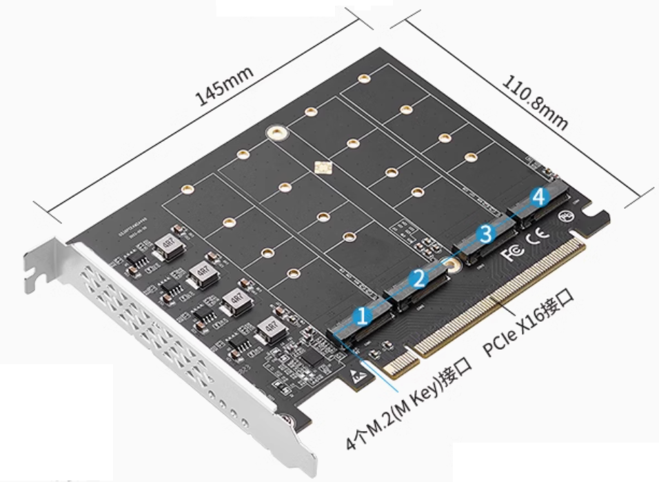
So how do you install multiple NVMe SSDs on one motherboard?
Many motherboards have M.2 M Key slots, but usually, there are only 2 at most. NVMe SSDs use PCIe lanes, and many motherboards have plenty of PCIe slots, so can they be converted?
It turns out there are indeed options, like the one shown below.
As long as the motherboard supports PCIe lane splitting, you can plug in a bunch of SSDs.
1.3 Motherboard Selection
Now it is clear that the network card needs to be plugged in, and the SSD needs to be plugged in, so the motherboard must have plenty of PCIe slots. And I am a person who pursues perfection, I set myself a challenge of keeping the size within 3.5 inches, after all, the smaller, the cooler.
I initially considered going the ARM route, like the Raspberry Pi CM series. But seeing that it only has 1 PCIe 2.0 x1 lane, I was instantly discouraged; checking other ARM modules, the documentation and compatibility made me sweat, and I had to answer a bunch of project information just to buy a module…So I decisively looked into the x86 route.
By chance, I saw the LattePanda Mu on Toutiao, and it was exactly what I was looking for.
It uses an N100 quad-core processor, and the gold finger interface can be configured to have up to nine PCIe x1 lanes, or can be configured to 2 PCIe x4, 4 PCIe x2, etc., very flexible. The official also open-sourced the schematic and PCB source files, and the BIOS is also not hidden, with a price that is still acceptable.
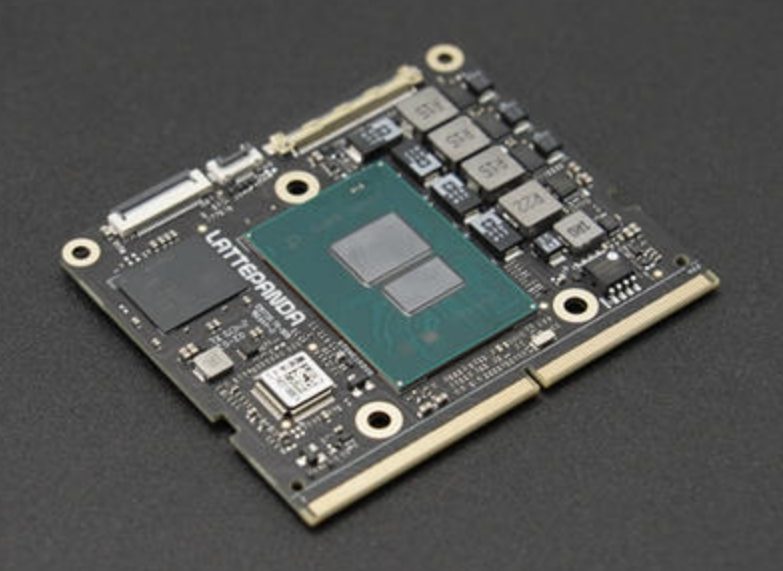
Interestingly, they also released a high-performance version: Core i3 N305 processor, 8 cores, 16GB RAM, with seamless switching of size and interfaces. One day when I feel adventurous, I might upgrade to i5 or i7, and who knows, it might be compatible,leaving room for upgrade possibilities.
02 Routing Techniques
High-speed signal lines are not too difficult to route; besides the aforementioned impedance, length matching, width, and spacing requirements, understanding the following few considerations will help you easily draw your first functioning motherboard.
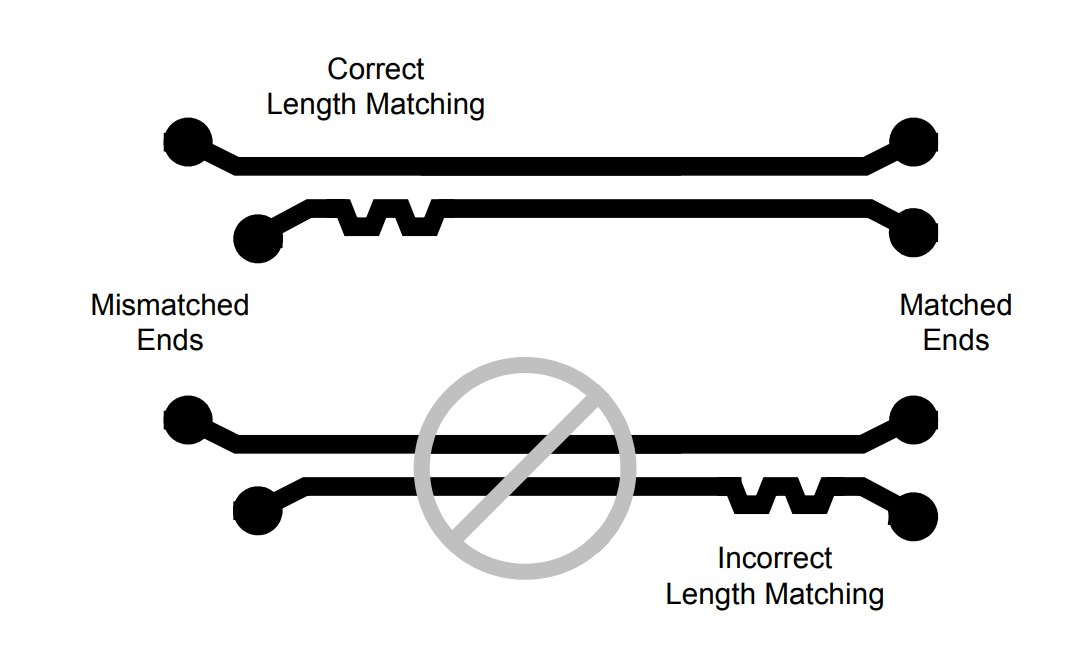
For differential pairs, when performing length compensation, start from the source end, meaning: wherever the lengths start to differ, begin to loop for equal length from there.
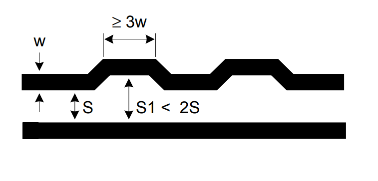
When performing length compensation, prioritize equal length, which will definitely sacrifice impedance values, but it is important to note that there are still requirements; for protruding segments: the maximum spacing should be less than 2 times the normal spacing, and the length should be greater than 3 times the line width.

AC coupling capacitors must be aligned (aligned), and cannot be staggered.
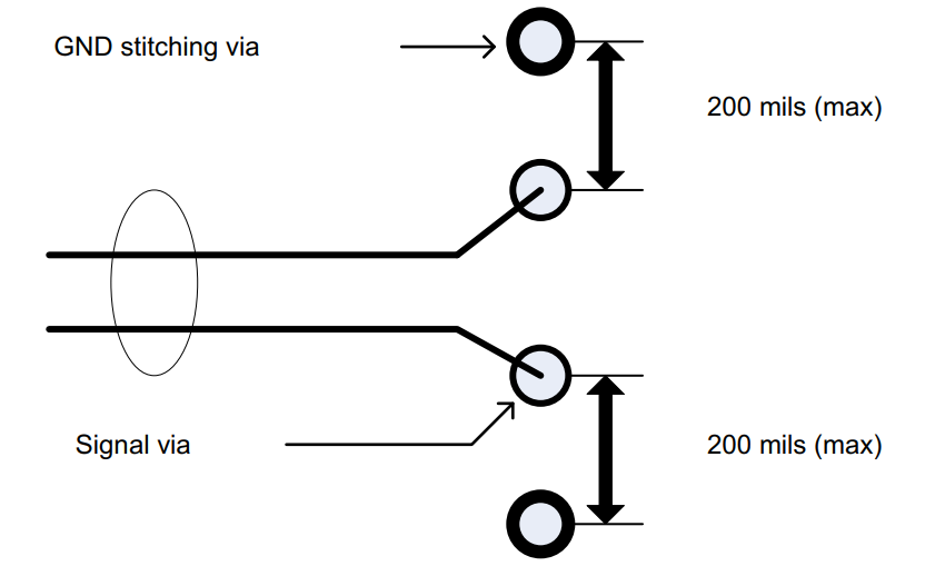
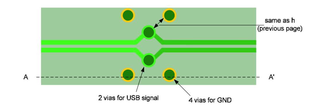
When signal lines transition layers, you must place 2 return vias (GND vias) near the signal via. Of course, placing 4 GND vias would be even better.
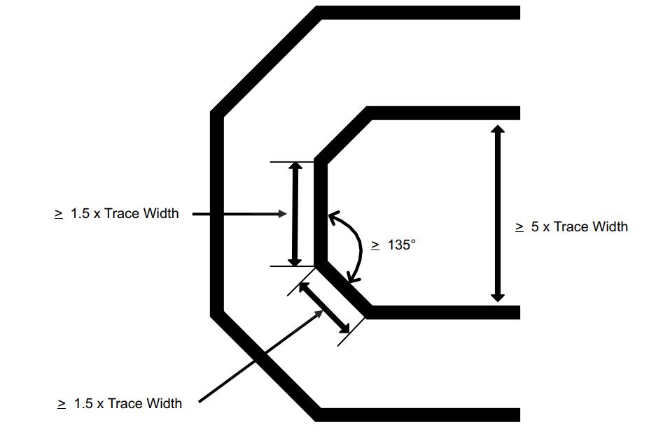
When differential pairs make turns, the shorter signal line segment should be at least 1.5 times the line width.
The spacing between differential pairs should be 5 times the line width (the center-to-center spacing, commonly referred to as 5W), to reduce crosstalk, especially when the parallel routing length is long.
Of course, in some cases, it may not be possible to meet 5W, but if the parallel routing segments are relatively short, 3W is also acceptable.
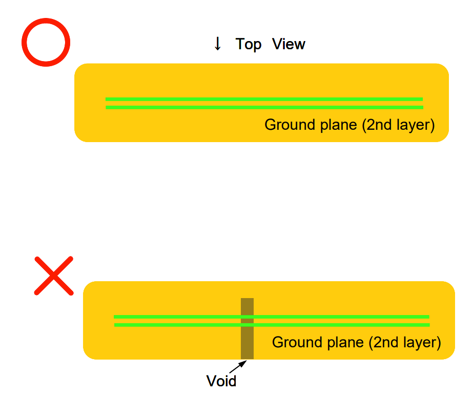
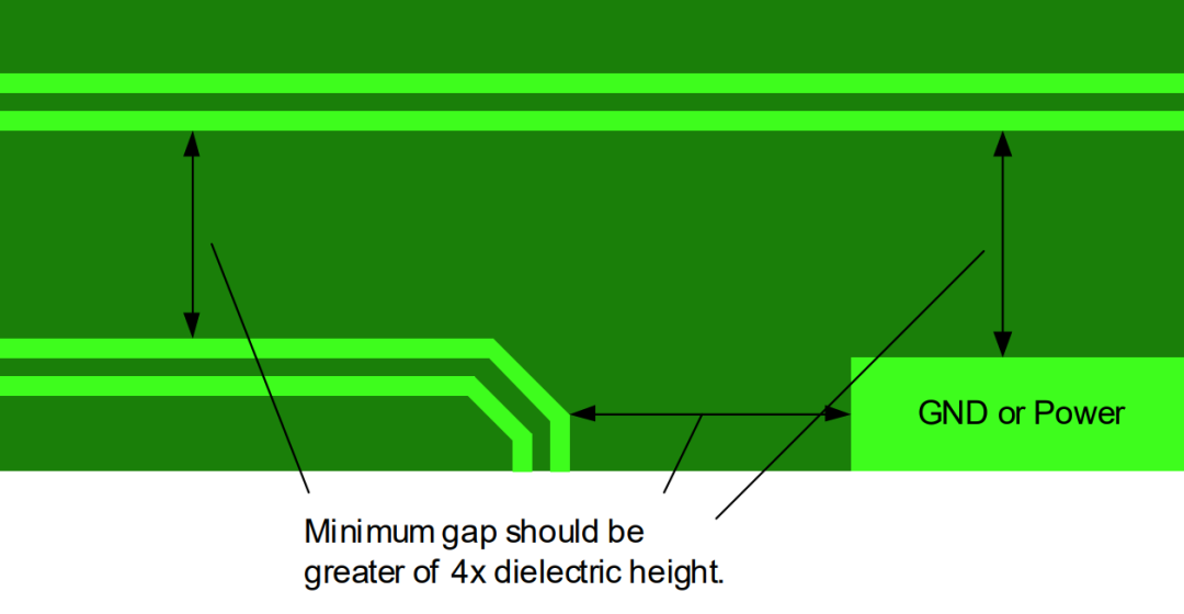
There must be a complete reference plane below the signal line (usually a GND plane), otherwise it will cause impedance changes, leading to signal reflections, causing instability or even failure to operate normally.
Additionally, for external device interfaces, such as USB, HDMI, buttons, etc., it is strongly recommended to add ESD protection tubes!
Motherboard Effect Diagram ▼
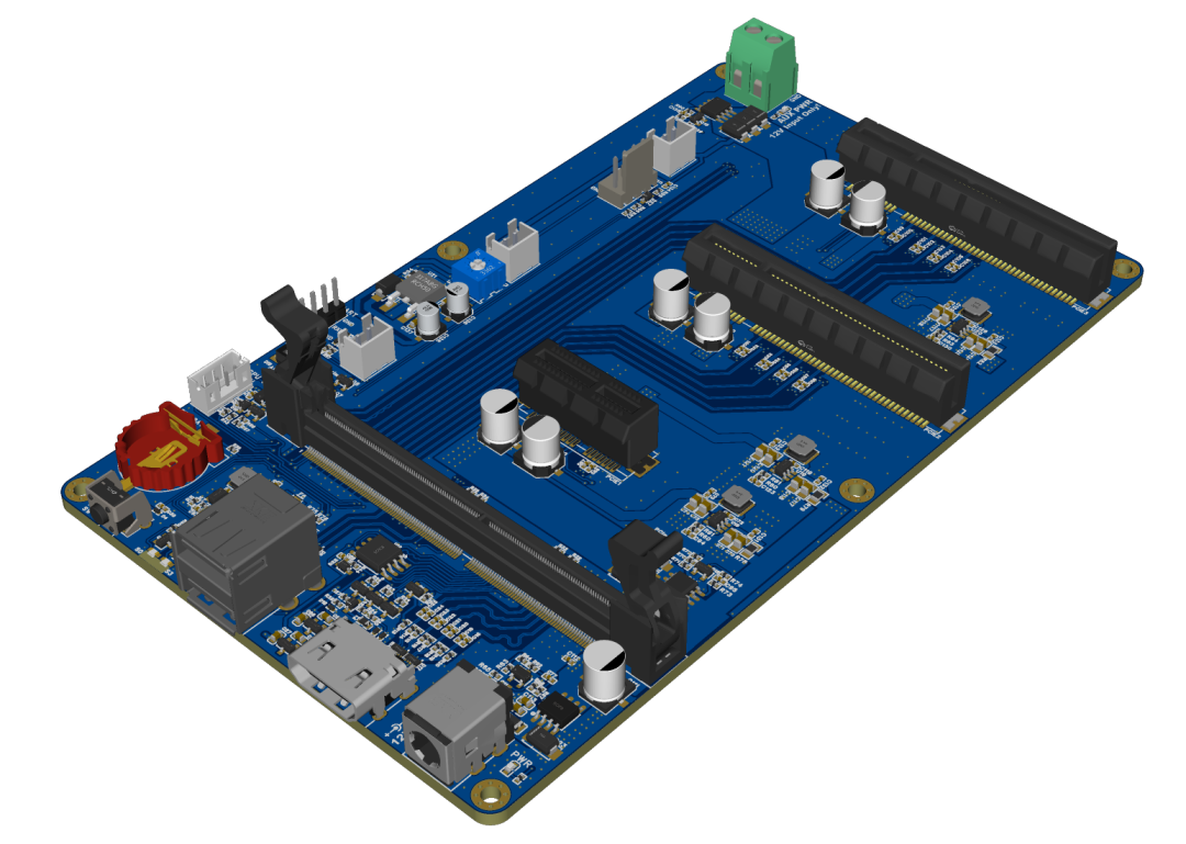
This is my first time designing such a high-speed board, and the PCB design took a full 3 weeks.
Since PCB design goes from 0 to 1, there are too many details to cover, and it is difficult to explain clearly in text and images; video would be more suitable. Therefore, once this version passes the prototype testing, I will consider producing a video tutorial to let everyone enjoy the fun of DIY.
Editor’s Note:
Welcome everyone to visit the open-source website (Chapter 3) to urge updates~~~
We also want to see it, hehe

02Function Demonstration”
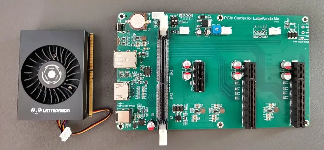
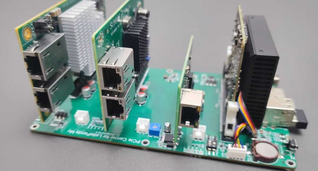
On the left is the Mu module + cooling fan. On the right is the PCIe expansion board open-sourced for this project, equipped with three PCIe slots.
High-Speed Soft Router
Physical Demonstration
Insert a gigabit network card or even a 10G network card into the PCIe slot, and easily set up a high-speed soft router!
Pure Solid-State NAS
Physical Demonstration
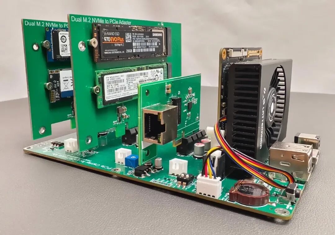
Insert NVMe expansion boards and network cards into the PCIe slots, and easily set up a high-speed pure solid-state NAS.
Of course, there are many more combinations possible!
03Open Source Website”
This project has been open-sourced!
——Want to replicate it? Want to give the author a thumbs up? You can copy the open-source website to go to the original text.
Open Source Website: https://oshwhub.com/mr_light_up/flexpcieboard
Scan the code to directly access the original text.


*This article is a reprint of user creations from the “Lichuang Open Source Hardware Platform”; descriptions may have been edited or may not be the latest version; please refer to the specific project descriptions on the Lichuang Open Source Hardware Platform..
All images, fonts, trademarks, and other assets involved in the project and project descriptions belong to their respective owners; if there is any infringement, please contact for removal.
The project open-source agreement is subject to the specific project descriptions and requirements of the open-source hardware platform.
If you see this, please give me a thumbs up! Click to read the original text to view the original project